
Multi-stage vacuum distilling, cooling and freezing processes and apparatuses for solution separation and seawater desalination

a vacuum distilling and seawater desalination technology, applied in vacuum distillation separation, domestic cooling apparatus, separation processes, etc., can solve the problems of large amount of energy consumed, uneconomically consumed, necessary and highly uneconomically to consume more energy to complete the separation of water, etc., and achieve the effect of not consuming too much energy

Inactive Publication Date: 2006-04-13
CHOU CHENG MING
View PDF11 Cites 6 Cited by
  • Summary
  • Abstract
  • Description
  • Claims
  • Application Information

AI Technical Summary

Benefits of technology

[0006] A first object of the present invention is to achieve a desired solute concentration. To achieve this object without consuming too much energy and within a lower temperature range, a multi-stage vacuum distilling system is employed. In the system, the drain-to-vacuum process implemented using a degassed liquid to produce vacuums in evaporating vessels (because air pressure in the evaporating vessels is negligible). Since expanded ranges of temperature and pressure can be used in vacuum distillation, more stages of vacuum distillation are allowable. In the present invention, constant temperature distilling process, solution transfer, and recycling of hot circulating solution are performed to separate a solution to be separated and recover most part of heat energy for repeated use. Temperatures for vacuum distillation at multiple stages are set depending on a temperature gradient of the hot circulating solution, so that separation of a degassed solution is achieved in the form of multi-stage vacuum distillation. In this way, more solution can be separated with one unit of energy, and the low-temperature concentrated solution discharged in the solution separation can be subjected to vacuum freezing and drying for further solute concentration.
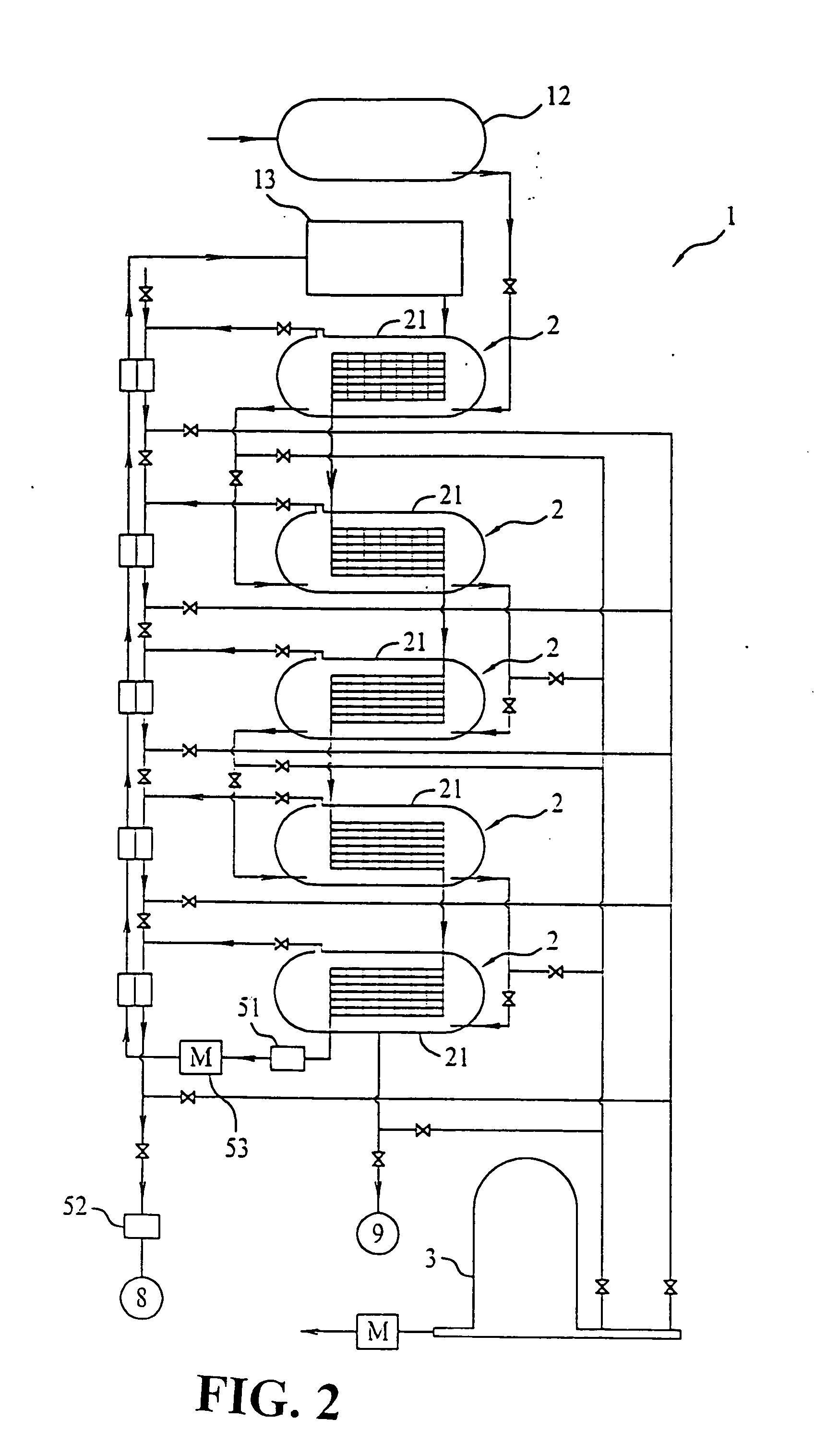
[0007] Another object of the present invention is to reduce costs for seawater desalination. Since the temperature and pressure ranges used in the present invention are expanded to facilitate increase of stages of vacuum distillation, the yield of pure water is increased. Meanwhile, since the evaporation heat for water is about seven times as high as the condensation heat for water, the employment of freezing would consume less energy than heating to produce the same amount of pure water. The present invention employs multi-stage vacuum freezing to produce low-temperature concentrated seawater and molten ice crystals to effectively reduce the temperature of hot circulating solution discharged at the last or lowest stage of multi-stage vacuum distillation. This in turn enables increased stages of vacuum distillation and yield of pure water. Finally, the low-temperature hot circulating solution recovers evaporation heat from the stages of vacuum distillation from bottom to top, so that most part of heat energy can be repeatedly utilized. The low-temperature solution, that is, the seawater, required in the multi-stage vacuum freezing is supplied from the last or the lowest stage of a multi-stage vacuum cooling process, and the ice crystals produced in the multi-stage vacuum freezing is molten with vapors produced in the multi-stage distilling and cooling processes. That is, the present invention combines multi-stage vacuum distilling, multi-stage vacuum cooling, and multi-stage vacuum freezing processes to effectively reduce costs for seawater desalination.
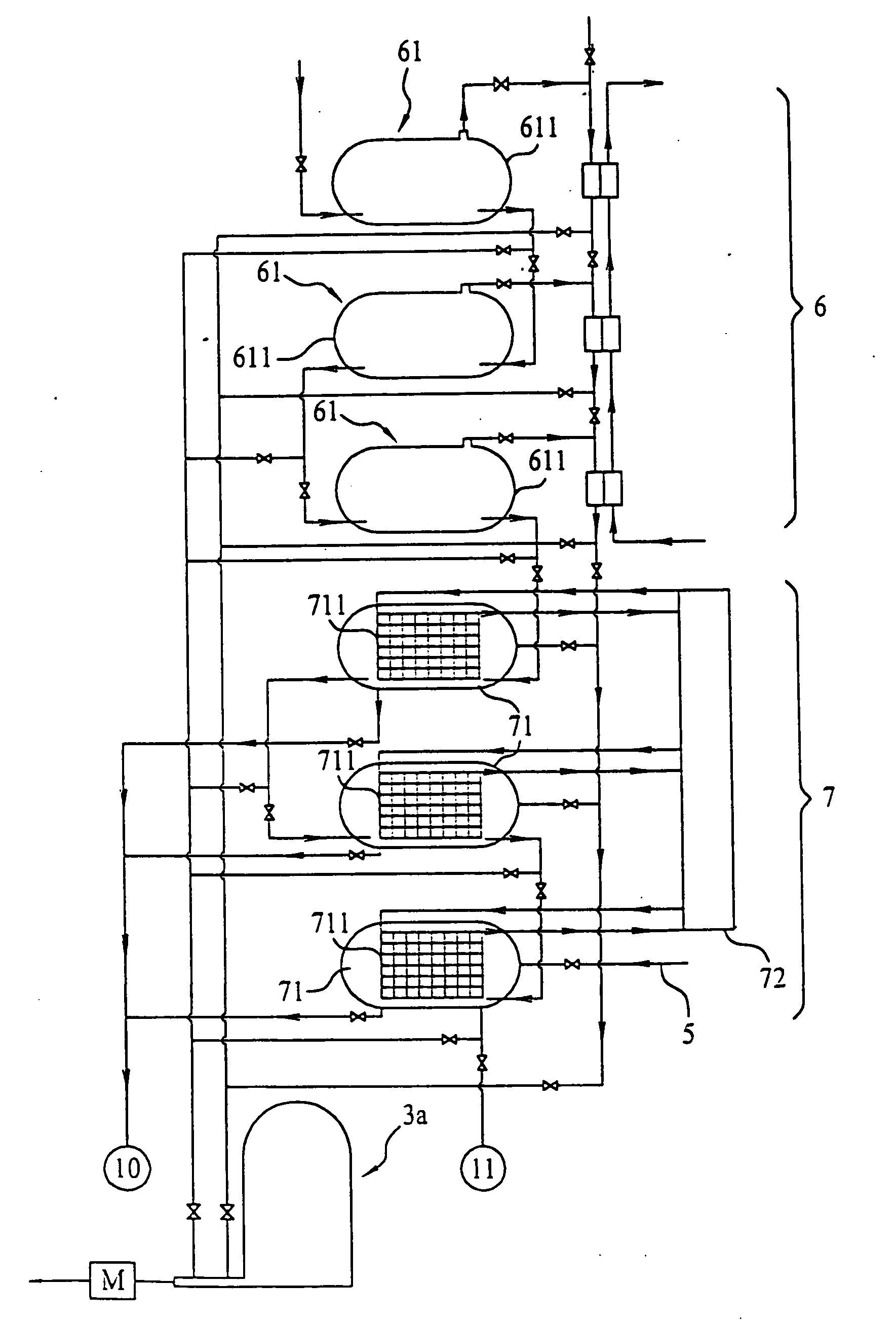
[0008] A further object of the present invention is to reduce the land cost for constructing a seawater desalination plant. In the multi-stage vacuum distilling, cooling, and freezing processes according to the present invention, the drain-to-vacuum process is implemented to produce vacuums in conduits, evaporating vessels, condensers, and freezing vessels included in the apparatuses and having a degassed solution, vapors, or condensate flown therethrough. The drain-to-vacuum process is based on the Torricellian vacuum principle that the pressure of atmosphere supports the column of liquid in the tube. In the apparatuses of the present invention, the first, second, third, and all subsequent stages of evaporating vessels or freezing vessels are stacked over one another from top to bottom like a tower to increase a height difference between these vessels and their common lower vessel and parts thereof. This stacked tower-like structure enables reduction of land area required to construct a seawater separation plant, also reduces energy required to produce vacuums. The tower-like multi-stage vacuum distilling, cooling, and freezing apparatuses enable the hot circulating solution, the solution to be separated (i.e. the seawater), and the condensate to continuously flow, which in turn minimizes the use of pumps and the occurrence of scales and corrosion in the apparatuses.

Problems solved by technology

When a large quantity of solution is separated through heating, a considerably high amount of energy would be uneconomically consumed.
To do so, a large amount of energy is consumed.
Thus, it is necessary and highly uneconomically to consume more energy to complete the separation of water from the seawater.
Further, various types of salt crystalline are produced in the process of heating seawater at high temperature to result in the problem of scaling, which in turn results in a condenser with largely reduced efficiency to produce only limited amount of water from separation of seawater and failure in fulfilling the high demand for water.

Method used


Image

  • Multi-stage vacuum distilling, cooling and freezing processes and apparatuses for solution separation and seawater desalination
  • Multi-stage vacuum distilling, cooling and freezing processes and apparatuses for solution separation and seawater desalination
  • Multi-stage vacuum distilling, cooling and freezing processes and apparatuses for solution separation and seawater desalination

Examples


Embodiment Construction

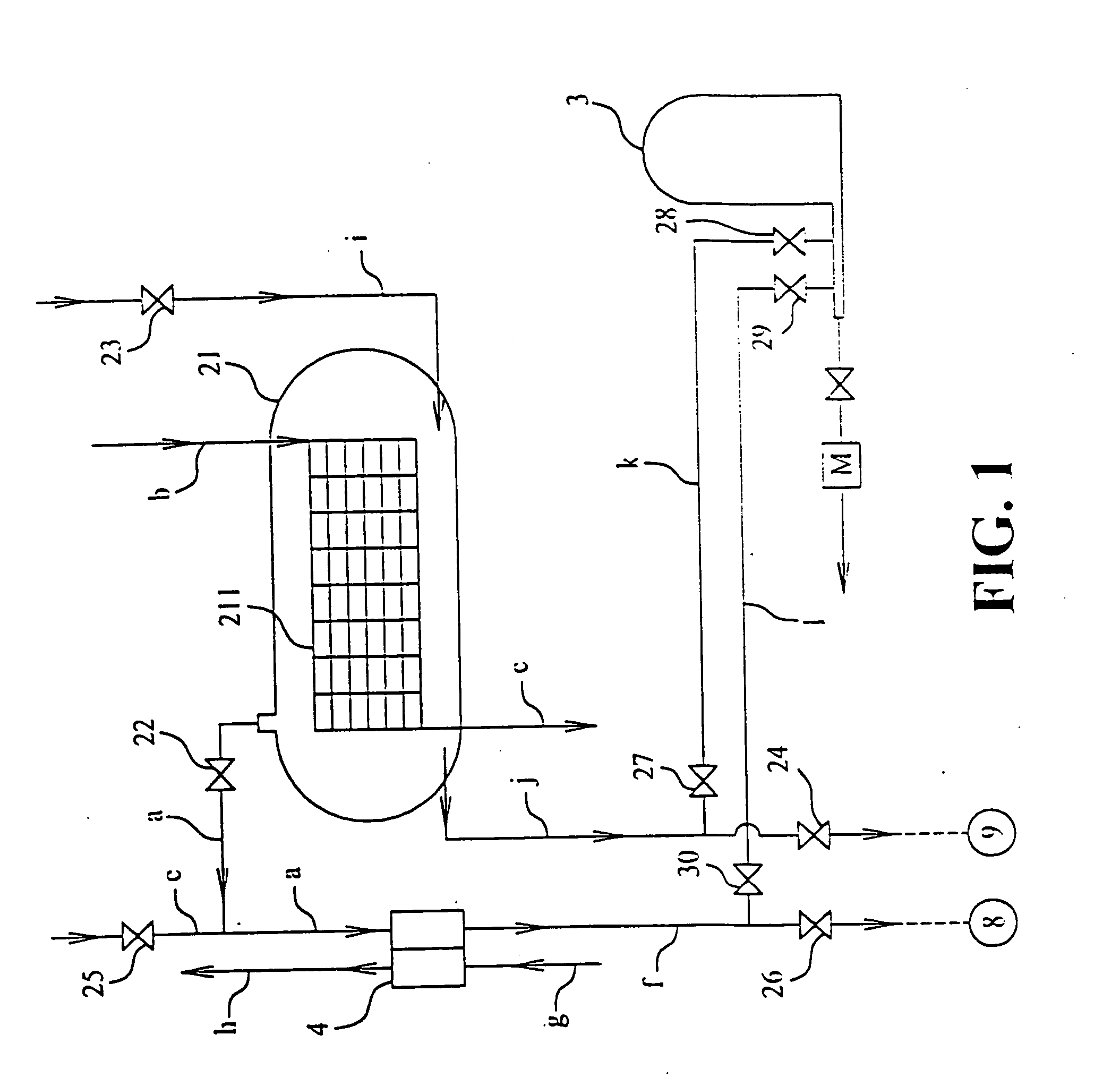
[0023] Please refer to FIG. 1 that is a schematic view of a constant temperature distillation unit for vacuum distillation 2 for implementing a constant temperature distilling process according to the present invention. The constant temperature distilling process is developed based on the principles that the boiling point of a liquid increases with the increased pressure, and that the temperature difference between two vacuum environments results in the difference in saturated vapor pressure therebetween. In this process, the constant temperature distillation unit for vacuum distillation 2 is used to cause a degassed solution in a vacuumized evaporating vessel to constantly boil and evaporate at a set temperature without changing a saturated vapor pressure of the evaporating vessel, so that a balanced thermal cycling between evaporation and condensation can be maintained.

[0024] As shown in FIG. 1, the constant temperature distillation unit for vacuum distillation 2 mainly includes ...


PUM

PropertyMeasurementUnit
constant temperatureaaaaaaaaaa
temperatureaaaaaaaaaa
liquid-aaaaaaaaaa

Abstract

Multi-stage vacuum distilling, cooling, and freezing processes for solution separation and seawater desalination are implemented through multi-stage vacuum distilling, cooling, and freezing systems. The systems are set to their initial state for implementing constant temperature distilling process, drain-to-vacuum and freezing process, transferring of a specific solution, and recycling of a hot circulating solution, so as to separate the specific solution. In the multi-stage cooling process, vacuum evaporation cooling is utilized to cool the solution in order to supply the low-temperature solution needed in the multi-stage vacuum freezing process. Vapors produced in the multi-stage vacuum distilling and cooling systems provide condensation heat needed to melt ice crystals produced in the multi-stage vacuum freezing system. And, the low-temperature concentrated solution and molten ice crystals produced in the multi-stage vacuum freezing system may be used to cool the hot circulating solution discharged at the lowest stage of the multi-stage vacuum distilling system.

Description

FIELD OF THE INVENTION [0001] The present invention relates to multi-stage vacuum distilling, cooling, and freezing processes for solution separation and seawater desalination, and more particularly to multi-stage vacuum distilling, cooling, and freezing processes for solution separation and seawater desalination in which a vacuum environment is provided in a vacuumized vessel obtained through a drain-to-vacuum process and a degassed solution is caused to flow through a liquid-gas interface or a liquid-solid interface to evaporate, cool, and freeze the degassed solution. The present invention also relates to apparatuses for implementing the aforesaid processes. BACKGROUND OF THE INVENTION [0002] Solution separating techniques have been widely employed in many fields, including general distillation, concentration of medical liquid, and desalination of seawater. [0003] When a large quantity of solution is separated through heating, a considerably high amount of energy would be unecono...

Claims


Application Information

Patent Timeline
Patent Type & Authority Applications(United States)
IPC IPC(8): C02F1/22B01D9/04F25D7/00B01D3/06B01D3/10B01D3/42C02F1/04
CPCB01D3/065B01D3/10B01D3/42C02F1/22C02F2103/08Y02A20/124Y02P70/10
Inventor CHOU, CHENG-MING
Owner CHOU CHENG MING
Learn More