
Self temperature control protection heater

a heater and self-temperature control technology, applied in the field of self-temperature control protection heaters, can solve the problems of inability to direct heat transmission to the object to be heated, heaters consume an extremely large portion of energy, and neither fails to meet modern li

Inactive Publication Date: 2006-04-13
MOBILETRON ELECTRONICS
View PDF10 Cites 1 Cited by
  • Summary
  • Abstract
  • Description
  • Claims
  • Application Information

AI Technical Summary

Benefits of technology

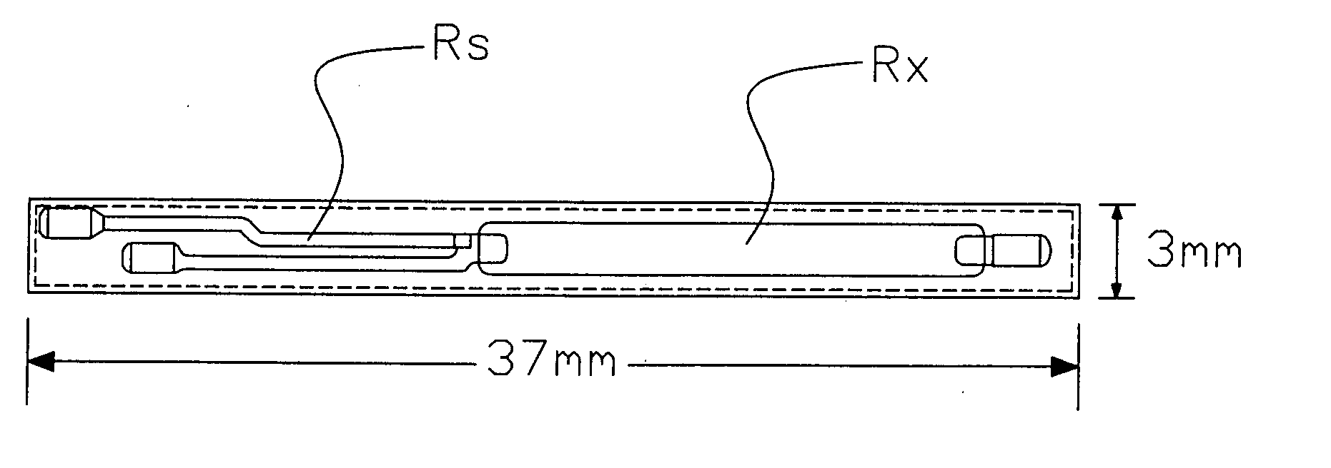
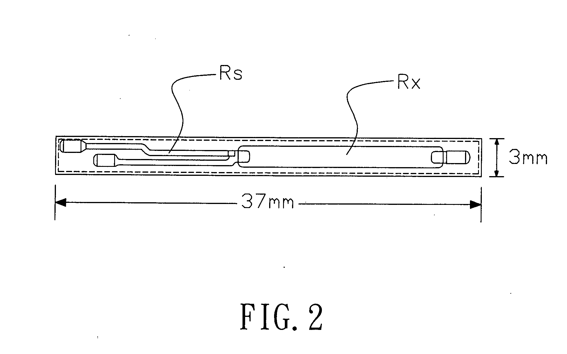
[0008] The primary purpose of the present invention is to provide a heater with self-temperature control protection that directly transmits thermal energy to the object to be heated in a heating efficiency much higher than the conventional heater. To achieve the purpose, the method of thick film metalized substrate is used. A flat (Ceramic Al2O3) substrate is sintered with thick film for conductor to serve as conduction wire; and a conductor paste or low ohm paste printed resistance (Rx), as the hot air generator. The ceramic substrate, being a good heat conductor, serves as an insulator, and also a heat transfer medium to directly contact the objected to be heated by instantaneously supplying high wattage (up to 100 W for the dimension of the preferred embodiment as illustrated in FIG. 2). Whereas the paste is sintered at 850° C., it is capable of withstanding heat up to 500° C. without deterioration in directly transferring the thermal energy to the object to be heated at a thermal efficiency higher than that of the prior art.
[0009] Another purpose of the present invention is to provide a heater with self-temperature control protection that achieves the dual purposes of self-protection and thermostat control. To achieve the purposes, the low resistance thick film paste, particularly, the conductor paste resistance has a high temperature coefficient resistance (TCR) to permit the optimal flexibility in temperature regulation to compromise the changes in temperature. Furthermore, a temperature sensor in the temperature controller is provided on the same substrate, and the control circuit precisely controls the temperature of the substrate not to exceed the preset upper limit of temperature. Accordingly, the heater is capable of providing higher wattage to secure self-protection before the temperature of the substrate increases to its preset upper limit; and the thermal electricity is conducted only after the heat transferred from the substrate to the object to be heated drops. Whereas the substrate maintains at a constant temperature to feed back a signal for joint control of the conduction of thermal electricity when the temperature of the object to be heated drops to a degree as desired for instantaneously providing high wattage.

Problems solved by technology

However, neither fails to satisfy modern life.
However, the heater consumes an extremely high portion of energy.
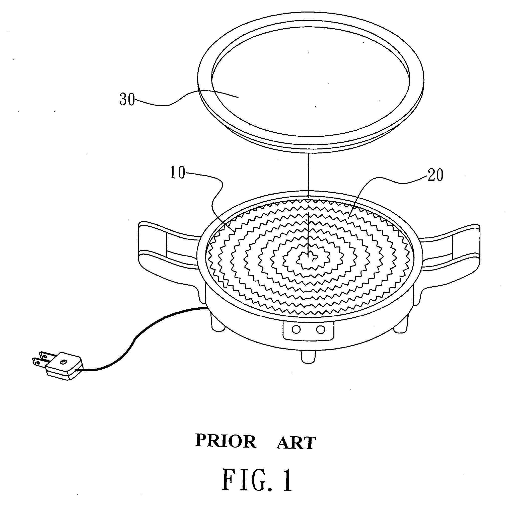
Consequently, direct heat transmission route to the object to be heated is impossible, meaning lots of thermal energy will be rendered useless.
Saving the concern, thicker heating wire contributes longer heating time; more thermal energy wasted; and lower heating efficiency.
Low safety: as the heating wire gets red hot at higher temperatures to become a source vulnerable to causing fire hazards while consuming the oxygen in the air to continuously create traces of gas combustion pollution.
When an electric cooking spoon is put into a pot containing water, traces of the metal coating of the heating tube will be dissolved into the boiling water to present health hazard to the user.

Method used


Image

  • Self temperature control protection heater
  • Self temperature control protection heater
  • Self temperature control protection heater

Examples


Embodiment Construction

[0018] The following descriptions are of exemplary embodiments only, and are not intended to limit the scope, applicability or configuration of the invention in any way. Rather, the following description provides a convenient illustration for implementing exemplary embodiments of the invention. Various changes to the described embodiments may be made in the function and arrangement of the elements described without departing from the scope of the invention as set forth in the appended claims.

[0019] Referring to FIG. 3, the present invention is essentially comprised of a thick film metalized substrate 100, a source circuit 210, a signal touch switch 220, a level detection circuit 230, a control circuit 240, a signal amplification circuit 250 and a temperature setup circuit 260. Wherein, the control circuit 240 relates to a single chip with matching functions. The source circuit relates to a bridge rectifier 211 to rectify the AC source into the power supply to the heater of the pres...


PUM


Abstract

A heater with self-temperature control protection comprised of a thick film metalized substrate, a signal touch switch, a level detection circuit, a control circuit, a signal amplification circuit and a temperature setup circuit to deliver electricity from the signal touch control respectively to both inputs of the control circuit to output to the signal touch switch for providing instantaneous self-protection at a given temperature with greater energy, smaller area, and higher efficiency than that of the conventional heater.

Description

BACKGROUND OF THE INVENTION [0001] (a) Technical Field of the Invention [0002] The present invention is related to a self-temperature control protection heater, and more particularly, to an innovative heating element adapted to a temperature controller for providing instantaeous self-protection of massive energy, small area, and high efficient at a specific temperature. [0003] (b) Description of the Prior Art [0004] Thermal energy, discovered by our ancestors, ranging from fire for cooking or fending off bitter cold winters and wild animals to natural sources, including terrestrial heat and sun light for keeping the globe warm enough for all creatures, is a must. However, neither fails to satisfy modern life. Upgraded capabilities to control energy technology help introduce various types of heaters allowing an easier and immediate access to thermal energy at a rated setting. The most popular heater relates to one that converts electricity into heat and the heater has become vital an...

Claims


Application Information

Patent Timeline
IPC IPC(8): H05B3/10
CPCH05B3/746H05B2213/07
Inventor CHIEN, SHUENN-TIANLU, WEN-JUNGEE, CHU-KUO
Owner MOBILETRON ELECTRONICS
Learn More