
Display apparatus

a display apparatus and liquid crystal technology, applied in the field of display apparatuses, can solve the problems of poor luminance uniformity, low luminance and light-using efficiency, and high cost of manufacturing the conventional backlight assembly, and achieve the effect of enhancing luminance and reducing thickness

Inactive Publication Date: 2006-04-13
SAMSUNG ELECTRONICS CO LTD
View PDF5 Cites 19 Cited by
  • Summary
  • Abstract
  • Description
  • Claims
  • Application Information

AI Technical Summary

Benefits of technology

[0011] The present invention provides a display apparatus having thin thickness and high luminance.
[0015] According to the display apparatuses of the present invention, a light source is integrally formed with an LCD panel. Therefore, thickness is reduced and luminance is enhanced.

Problems solved by technology

As a result, both luminance and light-using efficiency are lowered.
Further, the conventional backlight assembly has poor luminance uniformity, and a cost of manufacturing the conventional backlight assembly is high, thereby lowering productivity.
Furthermore, the conventional backlight assembly has a thick thickness, which also increases a thickness of the display apparatus employing the conventional backlight assembly.

Method used


Image

  • Display apparatus
  • Display apparatus
  • Display apparatus

Examples


Embodiment Construction

[0024] Hereinafter, the embodiments of the present invention will be described in detail with reference to the accompanied drawings. In the drawings, the thickness of layers, films, and regions are exaggerated for clarity. Like numerals refer to like elements throughout. It will be understood that when an element such as a layer, film, region, or substrate is referred to as being “on” another element, it can be directly on the other element or intervening elements may also be present.

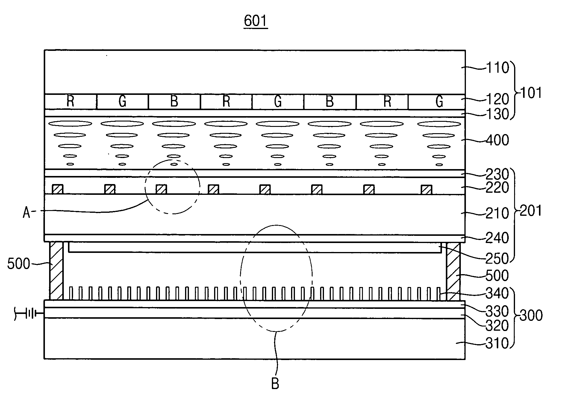
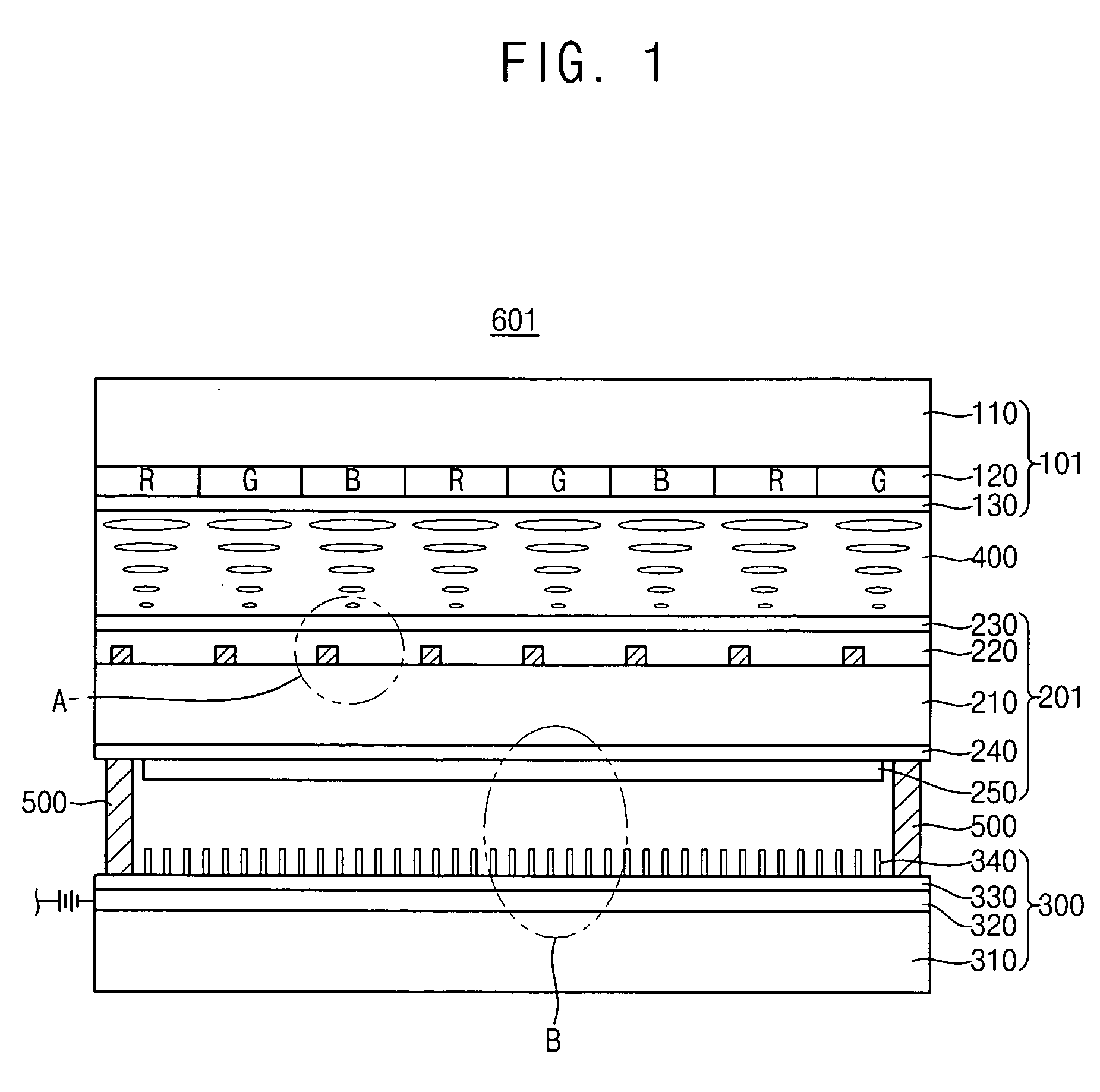
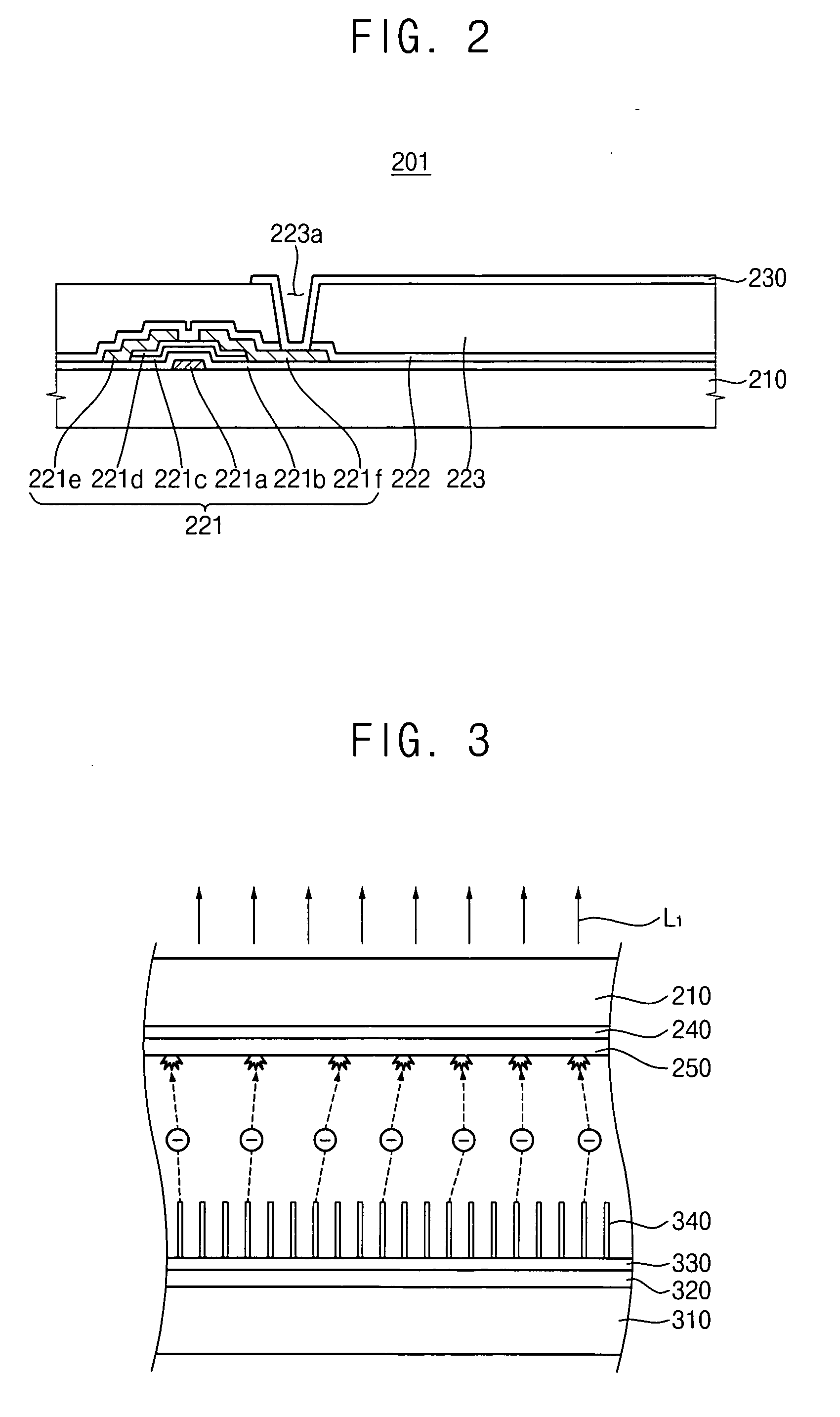
[0025]FIG. 1 is a schematic cross-sectional view illustrating a first exemplary embodiment of a display apparatus according to the present invention. FIG. 2 is an enlarged view illustrating portion ‘A’ in FIG. 1, and FIG. 3 is an enlarged view illustrating portion ‘B’ in FIG. 1.

[0026] Referring to FIG. 1, a display apparatus 601 includes a top substrate 101, a middle substrate 201, and a bottom substrate 300.

[0027] The top substrate 101 includes a first substrate 110, a color filter layer 120, and a ...


PUM


Abstract

A display apparatus includes a top substrate, a middle substrate, and a bottom substrate. The top substrate includes a first substrate. The middle substrate includes a second substrate, an anode electrode and a fluorescent layer. The second substrate includes an upper surface facing the first substrate and a lower surface that is opposite to the upper surface. An array layer is formed on either the upper surface of the second substrate or a lower surface of the first substrate. The anode electrode is formed on the lower surface of the second substrate. The fluorescent layer is formed on the anode electrode. The bottom substrate includes a third substrate and a cathode electrode formed on the third substrate such that the cathode electrode faces the fluorescent layer. Therefore, a thickness may be reduced and luminance of a light may be enhanced.

Description

[0001] This application claims priority to Korean Patent Application No. 2004-80534, filed on Oct. 8, 2004 and all the benefits accruing therefrom under 35 U.S.C. §119, and the contents of which in its entirety are herein incorporated by reference. BACKGROUND OF THE INVENTION [0002] 1. Field of the Invention [0003] The present invention relates to a display apparatus. More particularly, the present invention relates to a liquid crystal display apparatus employing an electroluminescent type backlight assembly. [0004] 2. Description of the Related Art [0005] Generally, a liquid crystal display (“LCD”) apparatus includes an LCD panel that displays an image and a backlight assembly that provides the LCD panel with light. [0006] A conventional backlight assembly employs a cold cathode fluorescent lamp (“CCFL”). The conventional backlight assembly employing the CCFL may be classified either as an edge illumination type backlight assembly or a direct illumination type backlight assembly ac...

Claims


Application Information

Patent Timeline
IPC IPC(8): H01J63/04H01J1/62
CPCG02F1/133617G02F1/133621H01J63/02H01J63/04H01J63/06G02F1/1335H01J1/30B82Y40/00
Inventor KIM, HYUN-JINNAM, SEOK-HYUNCHO, DON-CHANLEE, SANG-YU
Owner SAMSUNG ELECTRONICS CO LTD
Learn More