Optical means for calibrating temperature

a technology of optical means and temperature, applied in the direction of instruments, heat measurement, analysis using chemical indicators, etc., can solve the problems of difficult to accurately measure the temperature of a reaction mixture, difficult to achieve with a degree celsius accuracy, and not always easy to monitor the temperature of process microenvironments. to achieve the effect of being easily detectabl

Active Publication Date: 2006-04-13
QIAGEN GMBH
View PDF7 Cites 11 Cited by
  • Summary
  • Abstract
  • Description
  • Claims
  • Application Information

AI Technical Summary

Problems solved by technology

While it is generally easy to monitor the temperature of the overall environment of a process, it is not always easy to monitor the temperature of process microenvironments.
An example of a process where micro-environment temperature monitoring is desirable, but difficult to achieve with an accuracy of less than one degree Celsius, is a thermal cycling reaction such as for amplification of DNA.
Since reaction mixtures are rotated in the PCT / AU99 / 00277 device, it is difficult to accurately measure the temperature of a reaction mixture.

Method used


Image

  • Optical means for calibrating temperature
  • Optical means for calibrating temperature
  • Optical means for calibrating temperature

Examples


Embodiment Construction

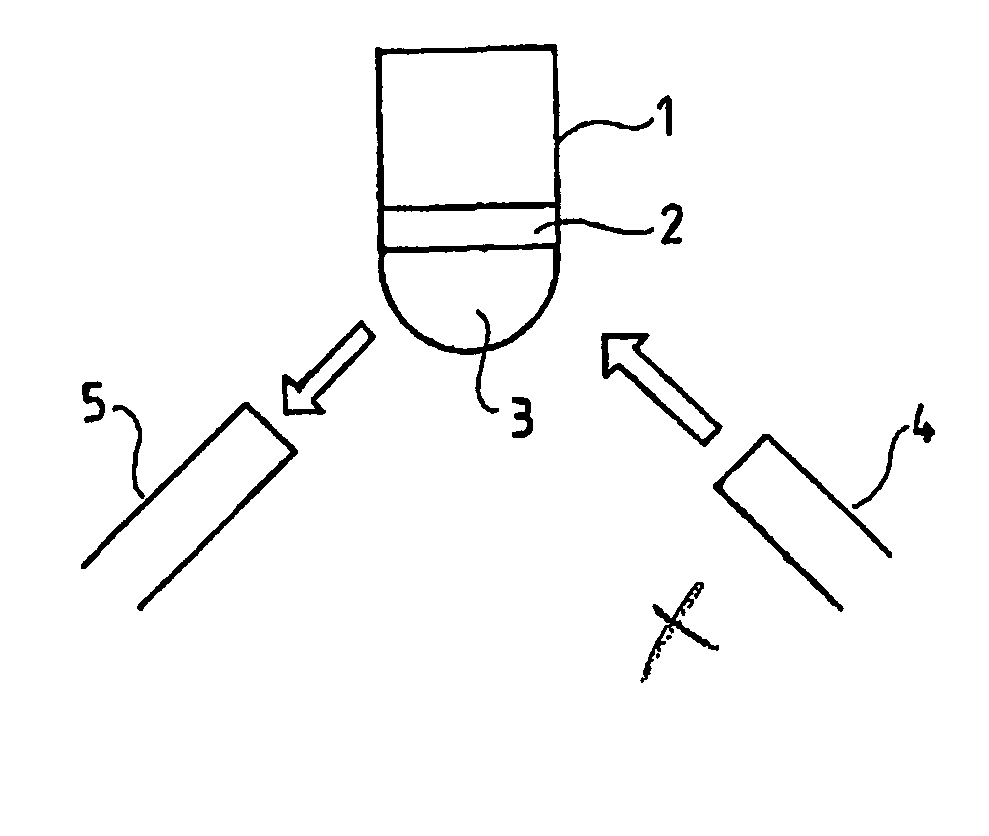
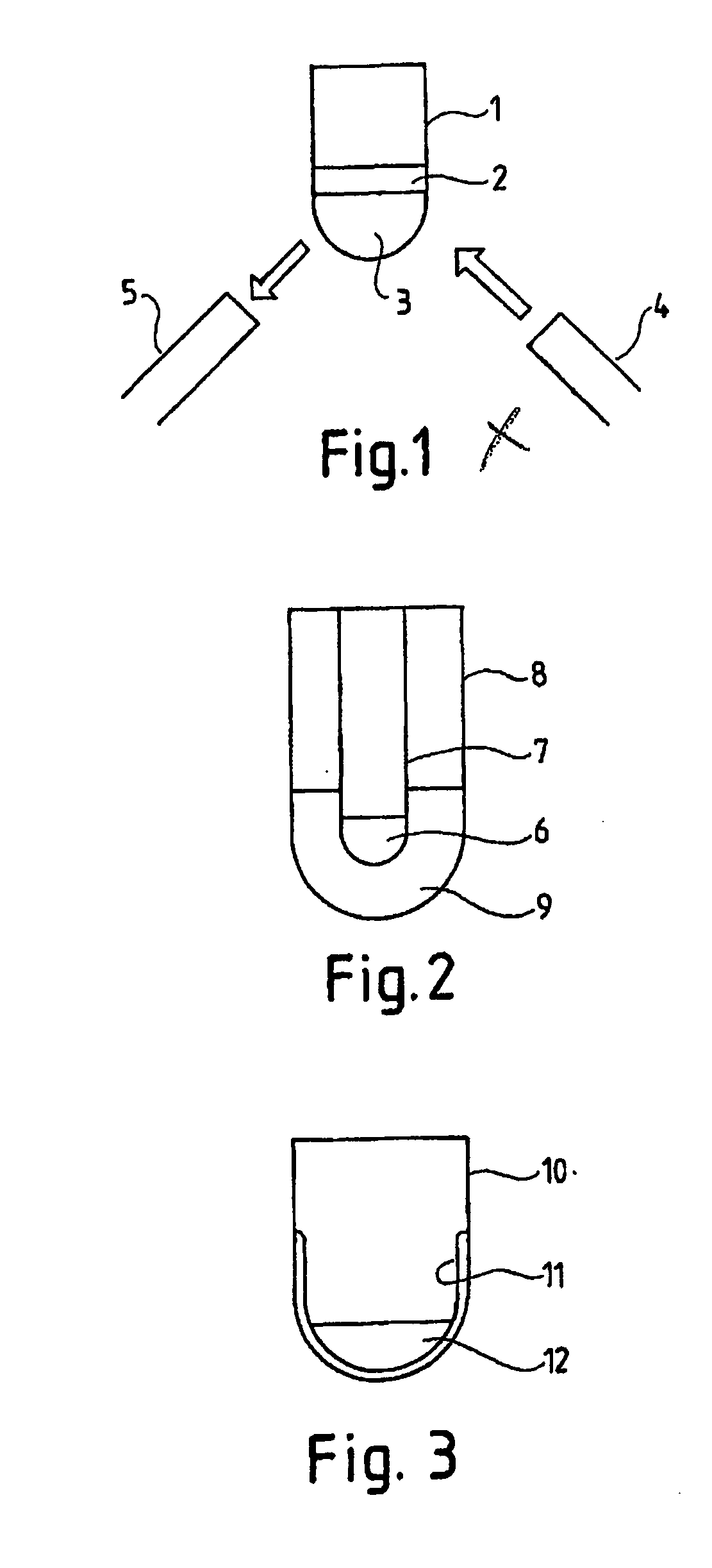
[0048] With reference to FIG. 1, there is shown a transparent vial 1 having therein a liquid luminophore-containing component 2 layered over a TLC component 3. The system comprising components 2 and 3 is irradiated by light source 4 and any luminescence emitted by component 2 detected by detector 5.

[0049] In FIG. 1, in the case where TLC 3 is a clearing point TLC, the system operates as follows. At temperatures below its transition temperature, TLC 3 will significantly block excitation of luminophore 2. At those temperatures, TLC 3 will also significantly block light emitted by luminophore 2 from reaching light detector 5. Conversely, at temperatures above the TLC's transition temperature, when the TLC is mostly clear, light source 4 will excite luminophore 2, and the emitted luminescence detected at detector 5. At the TLC's transition temperature, a small change in temperature will therefore result in a large change in detected luminescence. With a clearing point TLC, the system i...


PUM

PropertyMeasurementUnit
temperatureaaaaaaaaaa
wavelengthsaaaaaaaaaa
sensitive wavelength bandaaaaaaaaaa

Abstract

The invention relates to a system and method for the optical calibration of the temperature of a micro-environment. The system comprises a thermochromic liquid crystal in combination with a luminophore. The steps of the method comprise providing in combination in the micro-environment at least one thermochromic liquid crystal and a luminophore, varying the temperature of the environment while irradiating the combination with light that includes light at one or more excitation wavelengths of the luminophore, and monitoring luminescence emitted by the combination while recording the temperature of the environment.

Description

TECHNICAL FIELD [0001] The invention described herein relates to processes that are carried out at a temperature other than ambient. That is, processes which include raising or lowering the temperature in the environment of the process to a desired value. More particularly, the invention relates to a means for determining the actual temperature at specific locations within the environment of the process. BACKGROUND ART [0002] Many processes—particularly chemical processes—include steps that are carried out at a specific temperature. The efficacy of a particular step may in fact be dependent on the execution of the step at a specific temperature. It may be necessary to either heat or cool the environment in which the process is being carried out to the desired temperature. Monitoring of the temperature of the environment of a process is necessary so that heating or cooling can be terminated once the desired temperature is reached. Continued monitoring of the environment temperature i...

Claims


Application Information

Patent Timeline
Patent Type & Authority Applications(United States)
IPC IPC(8): G02F1/1335G01K11/12G01K11/16G01K11/20G01K15/00
CPCG01K11/165G01K11/20G01K15/005
Inventor RENNEBERG, CARL PETER
Owner QIAGEN GMBH
Why Eureka
Try Eureka