Optical devices, systems and method for producing a collimated light path

a technology of optical devices and light paths, applied in the field of optical devices, systems and methods for producing collimated light paths, can solve the problems of inability to change the separation between the ends of the source and the detector fiber without significantly altering the amount of light collected by the detector fiber

Inactive Publication Date: 2006-04-13
AGILENT TECH INC
View PDF9 Cites 52 Cited by
  • Summary
  • Abstract
  • Description
  • Claims
  • Application Information

AI Technical Summary

Benefits of technology

[0007] The invention provides a device for characterizing an optical property (e.g., such a light absorbance) of a liquid sample. In one aspect, the device is a spectrophotometer. However, the design of the device is generally applicable to other optical instruments such as fluorometers, spectrofluorometers, and photometers. In another aspect, the device comprises a sample containment area for receiving a sample container for small volume liquids, e.g., less than about 5 μl, less than about 2 μl, or less than about 1 μl. In one aspect, the sample containment area comprises two substantially parallel surfaces spaced apart by an adjustable distance, wherein sample liquid is confined by the surfaces and the surface tension of the liquid. In a further aspect, the device receives liquids comprising biological molecules, such as nucleic acids (RNA or DNA), polypeptides, or proteins.

Problems solved by technology

When dealing with very small sample volumes (e.g., from about 1 to 2 microliters), it is difficult to create cells or cuvettes small enough to be filled and to permit the industry standard 1 cm optical path to be used.
It is also difficult and / or time consuming to clean these cells or cuvettes for use with another sample.
One drawback with this close coupling approach is that the presence of the fiber ends in the samples can interfere with the insertion of the sample into the sample zone, cleaning of the sample zone, and other access to the sample zone.
Another drawback is the inability to change the separation between the ends of the source and detector fibers without significantly altering the amount of light gathered by the detector fiber.
Yet another drawback is that the instrument cannot easily be used to measure the transmission of solid samples with thickness greater than a few hundred microns.
This convoluted path increases optical loss (a function of the radius of curvature of bends in the fiber) and imposes constraints on the dimensions of the device, requiring the instrument to have a certain height in order for the optical fiber to approach the sample vertically.
Further, the exposed fiber presents the possibility of variable optical transmission as the optical fiber experiences movement as well as risk of breakage.
The instrument also may not be easily modified to include additional optical components.

Method used


Image

  • Optical devices, systems and method for producing a collimated light path
  • Optical devices, systems and method for producing a collimated light path
  • Optical devices, systems and method for producing a collimated light path

Examples


example 1

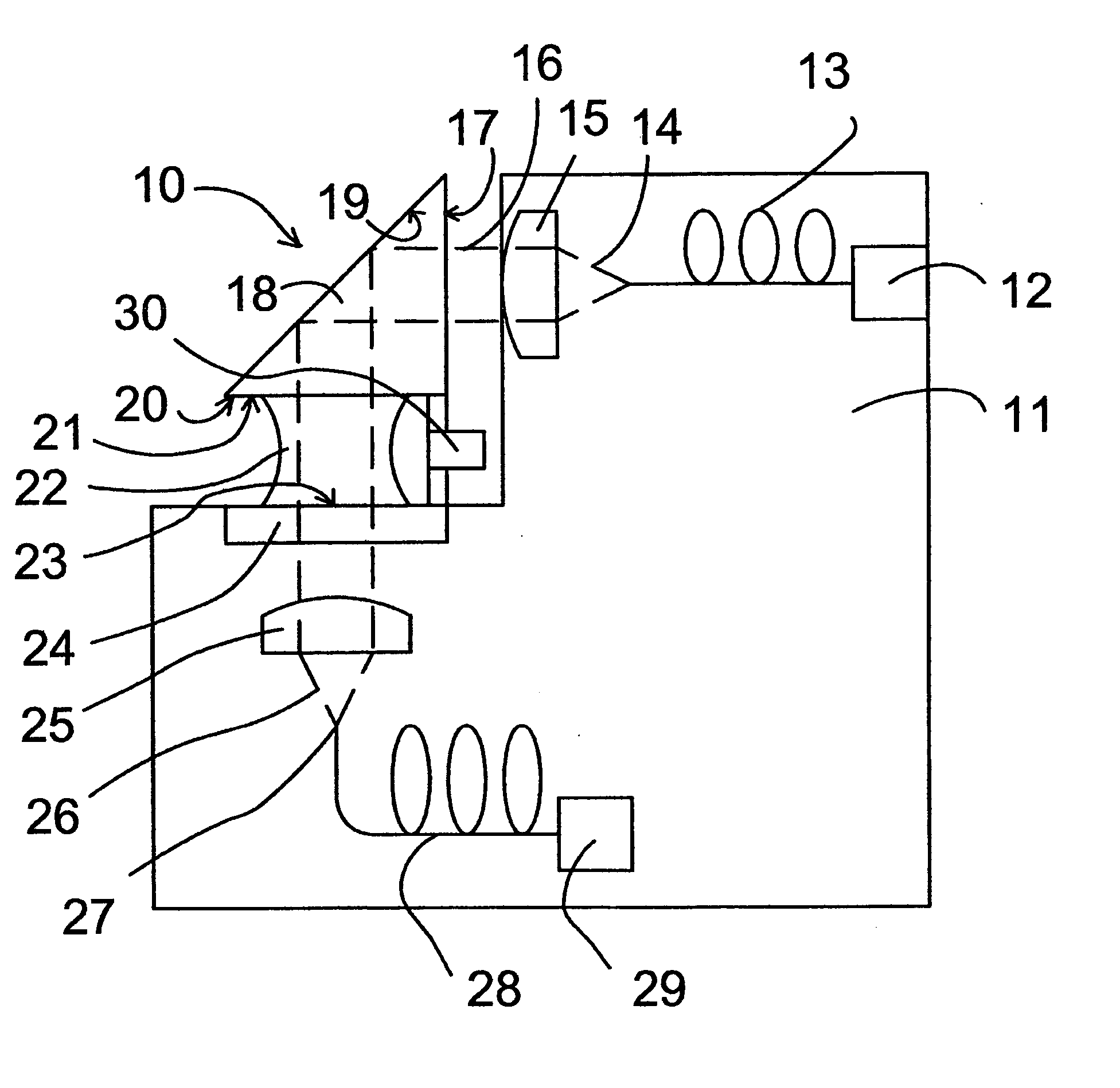
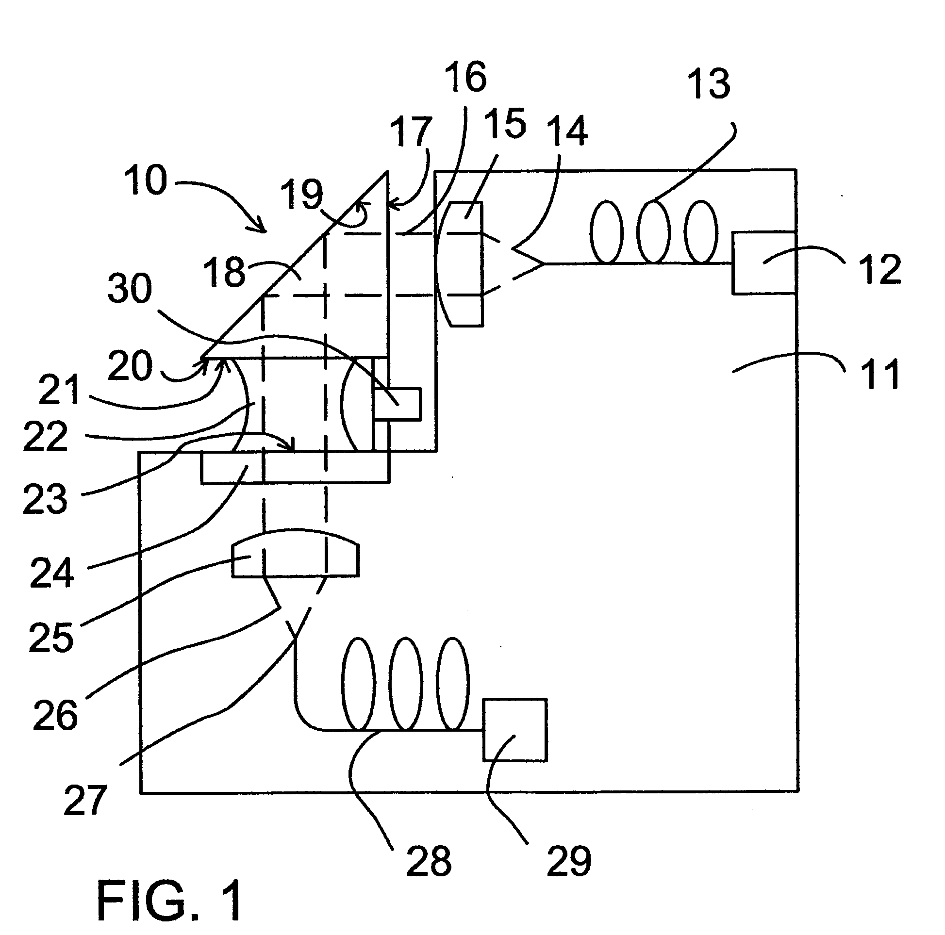
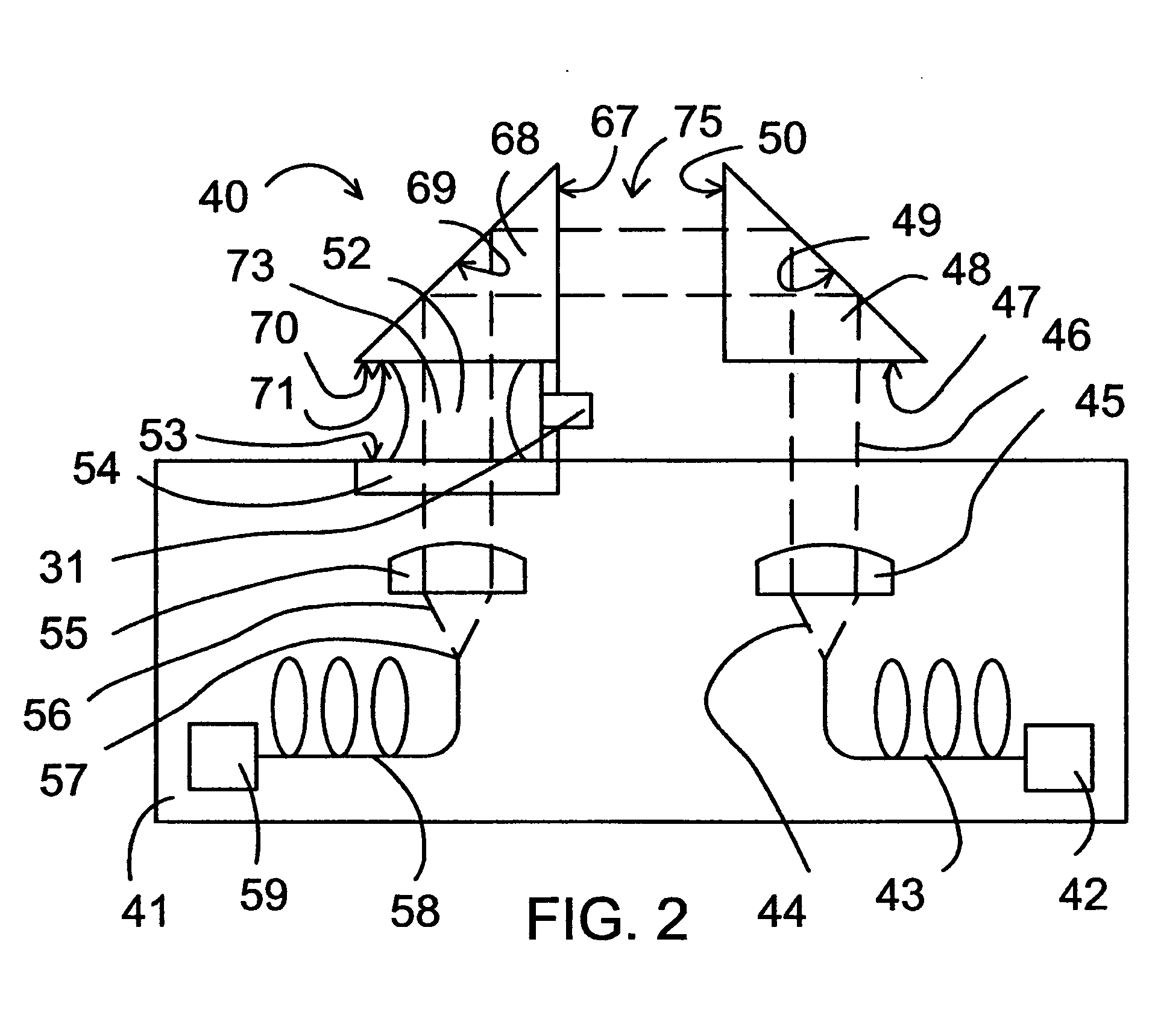
[0124] In order to explore the degree to which the divergent beam optics limited the use of a photometer design's in which the ends of the fiber were significantly separated, an experiment was conducted in which a broadband light source was coupled into a 200-micrometer-diameter multi-mode optical fiber; i.e. the source-side fiber. At the output of this fiber, it was observed that the light diverges. A second multi-mode optical fiber—the detection-side fiber—was placed a distance L from the source-side fiber and positioned so as to share the same centerline as the source-side fiber. Two detection-side fibers were tested: one with 200-micrometer core diameter and the other with 600-micrometer core diameter. A Silicon-photo-diode (Si-PD) at the output end of the detection-side fiber measured the spectrally integrated optical power coupled into the detection-side fiber.

[0125] Experimental data collected show that the optical power of the light beam dropped off quickly as fiber-to-fibe...


PUM

PropertyMeasurementUnit
path lengthaaaaaaaaaa
diameteraaaaaaaaaa
volumesaaaaaaaaaa

Abstract

Devices, systems and methods are provided for producing a collimated light path. Theses devices, systems and methods may be used to determine an optical property of a small volume sample.

Description

BACKGROUND OF INVENTION [0001] Liquid samples are often characterized using optical techniques such as photometry, spectrophotometry, fluorometry, or spectrofluorometry. Typically, the liquid is contained in a vessel referred to as a cell or cuvette, two or more of whose sides are of optical quality and permit the passage of those wavelengths needed to characterize the liquid contained therein. When dealing with very small sample volumes (e.g., from about 1 to 2 microliters), it is difficult to create cells or cuvettes small enough to be filled and to permit the industry standard 1 cm optical path to be used. It is also difficult and / or time consuming to clean these cells or cuvettes for use with another sample. [0002] Perspective on the problem of quantifying a 1-2 microliter liquid sample is gained by considering the physical size of such samples. For example, a 1 microliter droplet occupies a cube with 1 mm edge length or a cylindrical volume with height 1 mm and diameter 1.13 mm...

Claims


Application Information

Patent Timeline
Patent Type & Authority Applications(United States)
IPC IPC(8): G01N21/90
CPCG01N21/03G01N21/0303G01N2021/035G01N2201/08G01N2021/0346G01N2021/036
Inventor KRALIK, JOHN C.
Owner AGILENT TECH INC
Why Eureka
Try Eureka