Compressed data structure and apparatus and method related thereto

a waveform data and compression technology, applied in the field of memory-stored compressed waveform data structure, can solve the problems of complicated circuitry for decompressing compressed waveform data, limited start and end points, and the memory for storing waveform sample data must have an enormous storage capacity, etc., to achieve the effect of simple construction

Active Publication Date: 2006-04-20
YAMAHA CORP
View PDF8 Cites 11 Cited by
  • Summary
  • Abstract
  • Description
  • Claims
  • Application Information

AI Technical Summary

Benefits of technology

[0009] In view of the foregoing, it is an object of the present invention to provide an improved compression data structure, waveform gener

Problems solved by technology

The PCM method can advantageously generate tones very close to those of a natural musical instrument, but disadvantageous in that the memory for storing the waveform sample data must have an enormous storage capacity.
Thus, there arises a need for a circuit to calculate the respective leading addresses of the frames, which would greatly complicate the construction of circuitry for decompressing the compressed waveform data.
In the past, the frame-by-frame compression scheme would present the problem that the loop start and end points are restricted to boundary positions of the frames because of the necessity to reproduce the waveform data on the frame-by-frame basis.
Namely, because the loop start point and loop end point can not be set at appropriate sampling points, there would arise the problem that undesired noise is produced due to discontin

Method used


Image

  • Compressed data structure and apparatus and method related thereto
  • Compressed data structure and apparatus and method related thereto
  • Compressed data structure and apparatus and method related thereto

Examples


Embodiment Construction

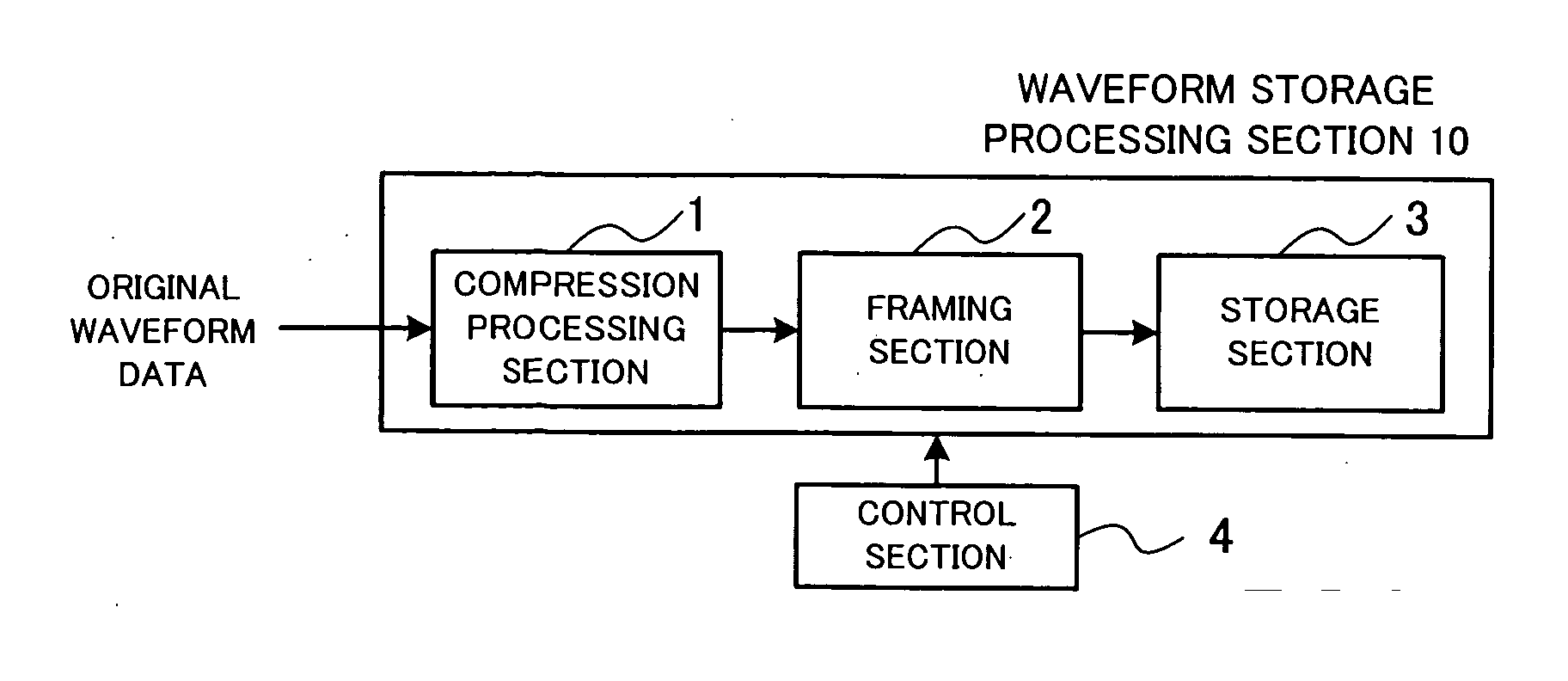
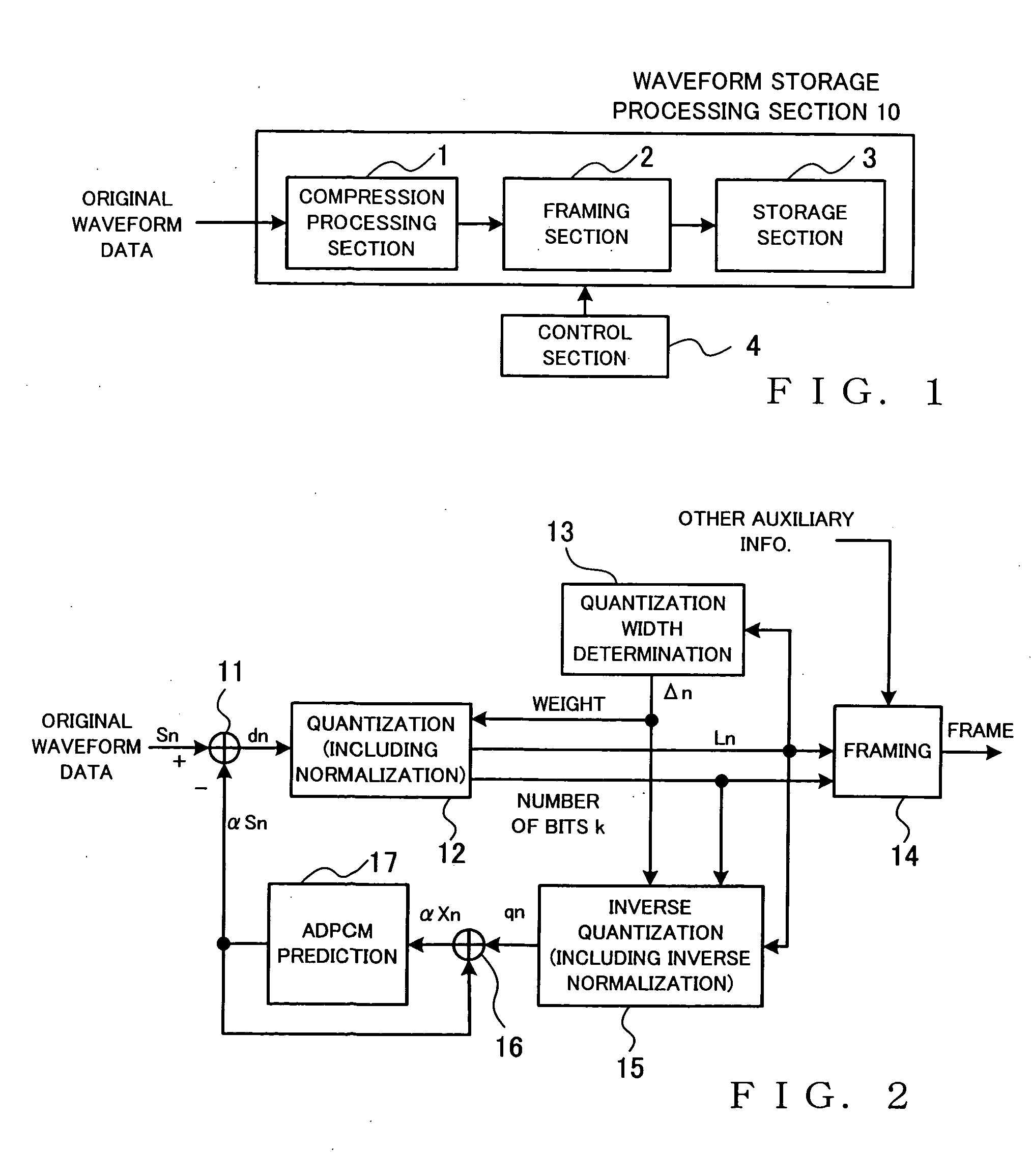
[0052]FIG. 1 is a block diagram showing a general setup of a waveform storage processing apparatus in accordance with an embodiment of the present invention.

[0053] As shown, the waveform storage processing apparatus includes a waveform storage processing section 10 and a control section 4. The waveform storage processing section 10 includes a compression processing section 1 for compressing input original waveform data into compressed waveform data of a variable length, framing (i.e., frame formation) section 2 for segmenting the compressed waveform data into a plurality of frames and classifying the segmented compressed waveform data of each of the frames as frame data along with auxiliary information, and a storage section 3 in which the data of each of the frames classified by the framing section 2 are written and stored. The control section 4 controls waveform storage processing, performed by the waveform storage processing section 10, to variably control, for each of the frame...


PUM


Abstract

Compressed waveform data structure is proposed which is suited for segmentation of a plurality of samples of compressed waveform data into a plurality of frames and subsequent storage of each of the frames. The number of bits per sample of the compressed waveform data is variable between the frames, but uniform, i.e. the same among all of the samples, within each of the frames. Each of the frames has a same data storage size. Each of the frames includes, in a predetermined layout, an auxiliary information area for storing auxiliary information that includes compression-related information to be used for decompressing the compressed waveform data, and a data area for storing a plurality of samples of the compressed waveform data of the frame with each of the samples comprising a same number of bits. Thus, respective start positions of the frames and compressed waveform data in a memory can be fixed at predetermined positions common to the frames, so that readout control can be performed with ease.

Description

CROSS REFERENCE TO RELATED APPLICATION [0001] This application is a division of application Ser. No. 10 / 676,205 filed on Sep. 30, 2003, the entire contents of which is incorporated herein by reference.BACKGROUND OF THE INVENTION [0002] The present invention relates to a structure of memory-stored compressed waveform data for use in tone generation apparatus etc., a tone generation apparatus for generating tones by reading out the compressed waveform data, and a waveform storage processing apparatus for writing compressed waveform data into a memory. The present invention also relates to a waveform data compression method, tone signal generation method and tone signal processing apparatus and program which are suitable for use in tone generation apparatus that store waveform data after compressing the waveform data on a frame-by-frame basis and reproduce the stored waveform data on the basis of performance information. [0003] Among the conventionally-known tone signal generation meth...

Claims


Application Information

Patent Timeline
IPC IPC(8): G10H7/00G10H7/02
CPCG10H7/02G10H7/12G10H2250/585G10H2250/595G10H2250/601G10H2250/621G10H2250/641
Inventor OKAZAKI, MASATSUGUSHIRAKAWA, TOKIO
Owner YAMAHA CORP
Why Eureka
Try Eureka