
Multilayer radiation shield

a radiation shield and multi-layer technology, applied in the direction of magnetic circuit rotating parts, container discharging methods, magnetic circuit shape/form/construction, etc., can solve the problems of reducing the efficiency of the rotating machine and ineffective conventional multi-layer insulation applications

Inactive Publication Date: 2006-04-20
GENERAL ELECTRIC CO
View PDF8 Cites 24 Cited by
  • Summary
  • Abstract
  • Description
  • Claims
  • Application Information

AI Technical Summary

Benefits of technology

[0007] There is a need, therefore, for an improved technique for insulating a superconductive rotor coil for a rotating electrical machine. There is a particular need for a multilayer technique, which can be employed to insulate a superconductive rotor coils that does not crush under centripetal loads present in rotating machines.

Problems solved by technology

However, the electrical resistance of copper is sufficient to produce a substantial amount of resistive heat losses in the rotor coil, which reduces the efficiency of the rotating machine.
However, a number of problems are associated with providing a low conductivity physical spacer to maintain a separation between successive layers of insulating sheets of a multi-layer insulation application.
Most notably, conventional multi-layer insulation applications will crush under centripetal loads present in rotating electrical machines, rendering the conventional multi-layer insulation application ineffective.

Method used


Image

  • Multilayer radiation shield
  • Multilayer radiation shield
  • Multilayer radiation shield

Examples


Embodiment Construction

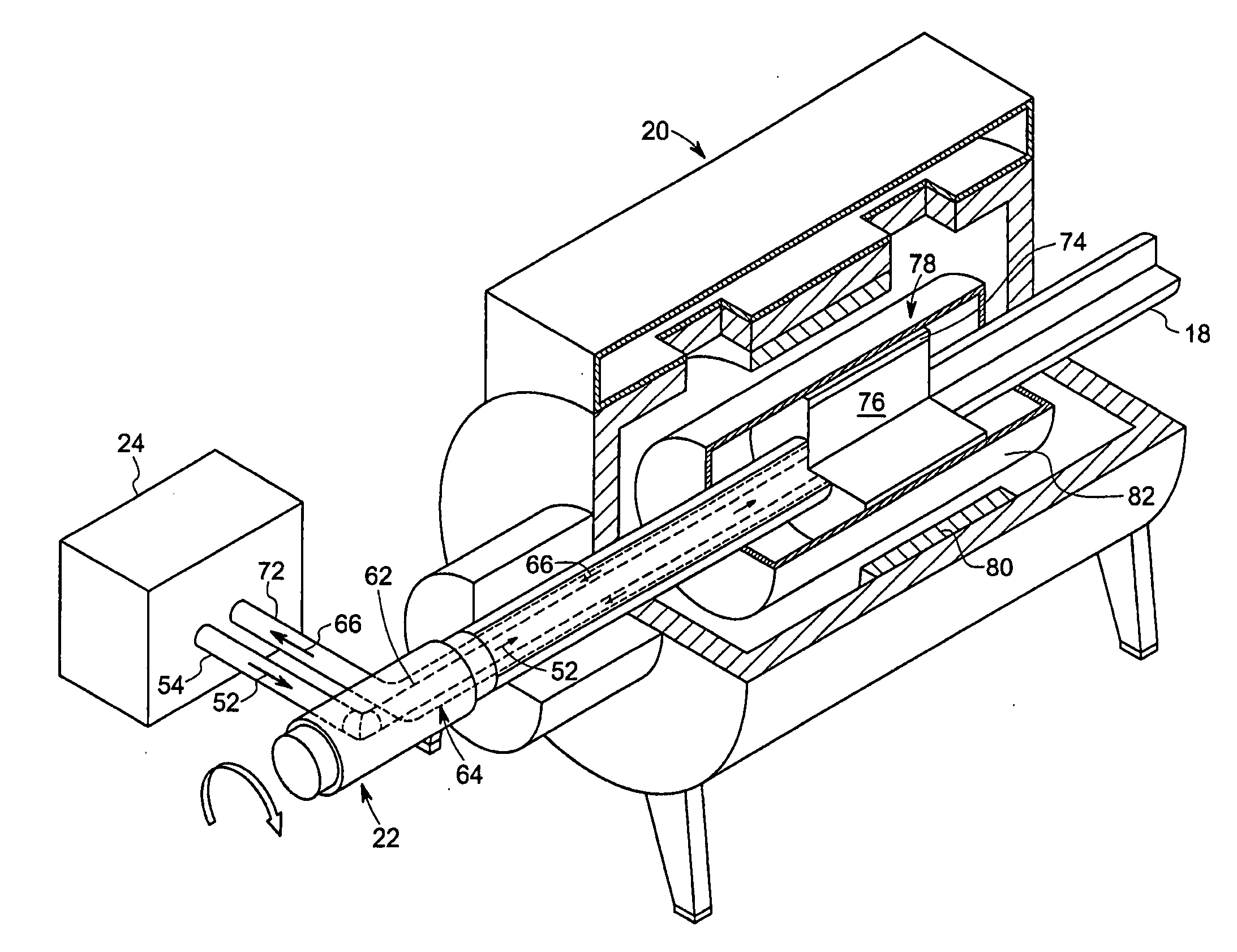
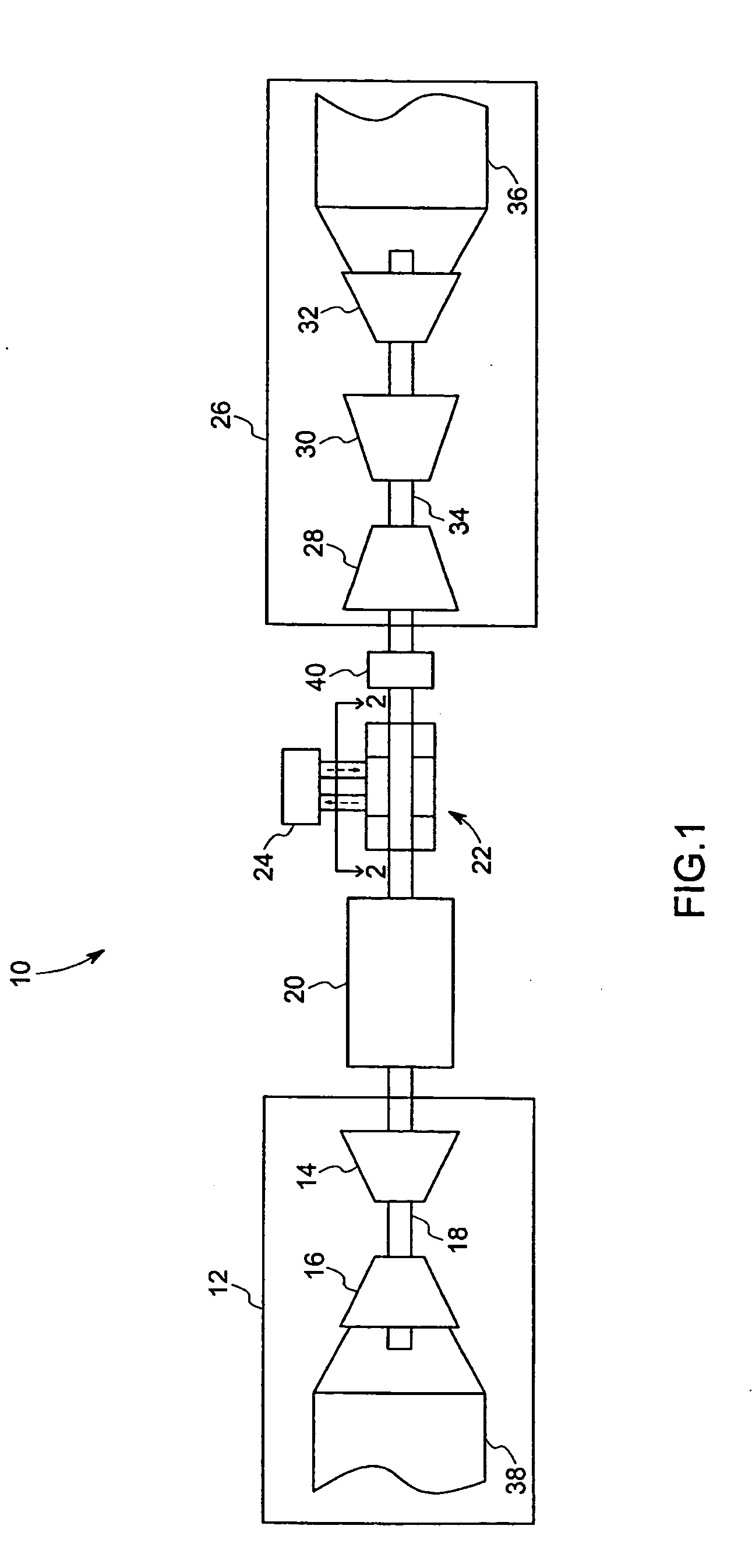
[0017] Turning now to the drawings, FIG. 1 illustrates a power generation system, represented generally by reference numeral 10. In the illustrated embodiment, the power generation system 10 comprises a gas turbine system 12 that uses the combustion of a gas to generate power. The illustrated gas turbine system 12 comprises a compressor 14 that is coupled to a gas turbine 16 via a rotatable shaft 18. The gas turbine 16 converts the energy produced by the combustion into rotation of the shaft 18. The compressor 14 raises the pressure of the air flowing into the gas turbine 16 for combustion, improving the efficiency of the combustion process.

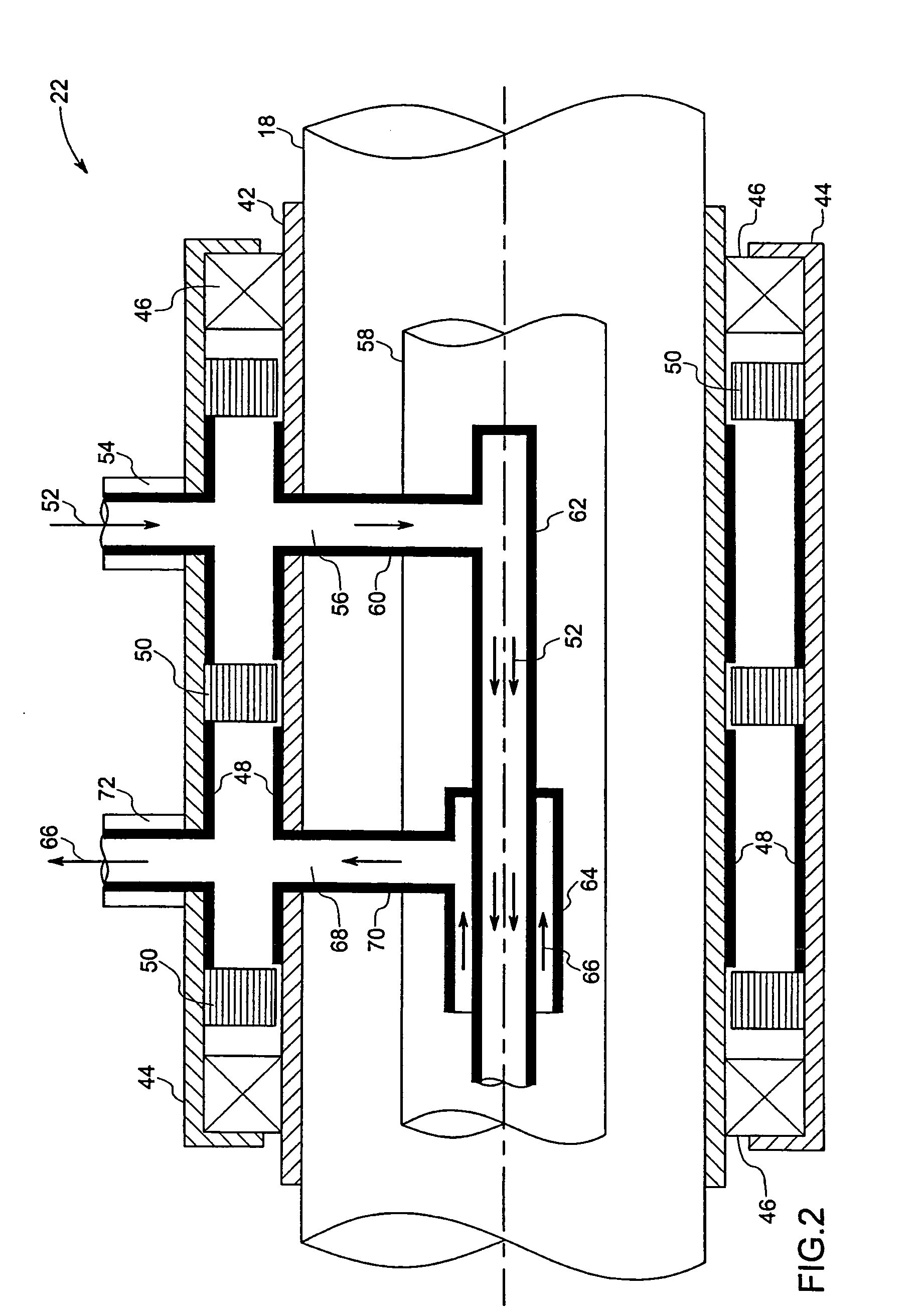
[0018] The shaft 18 of the gas turbine systeml2 is coupled to a generator 20, which converts the rotational energy in the shaft 18 into electricity. As will be discussed in more detail below, the generator 20 has a superconductive rotor coil that receives cryogenic fluid to cool the superconductive rotor coil to a superconducting state. The cryo...


PUM


Abstract

A power generation system including: a generator including a rotor including a superconductive rotor coil coupled to a rotatable shaft; a first prime mover drivingly coupled to the rotatable shaft; and a thermal radiation shield, partially surrounding the rotor coil, comprising at least a first sheet and a second sheet spaced apart from the first sheet by centripetal force produced by the rotatable shaft. A thermal radiation shield for a generator comprising a rotor including a super-conductive rotor coil comprising: a first sheet having at least one surface formed from a low emissivity material; and at least one additional sheet having at least one surface formed from a low emissivity material spaced apart from the first sheet by centripetal force produced by the rotatable shaft, wherein each successive sheet is an incrementally greater circumferental arc length and wherein the centripetal force shapes the sheets into a substantially catenary shape.

Description

STATEMENT REGARDING FEDERALLY SPONSORED RESEARCH & DEVELOPMENT [0001] This invention was made with Government support under contract number DE-FC36-02G011100 awarded by U.S. Department of Energy. The Government has certain rights in the invention.BACKGROUND [0002] The present invention relates generally to a rotating electrical machine employing a superconductive coil. More particularly, the present invention relates to a multilayer radiation shield for insulating a superconductive rotor coil for a rotating electrical machine. [0003] Rotating electrical machines, such as motors and generators, have a rotor and a stator that are magnetically coupled. Typically, the rotor has a coil that is used to produce a magnetic field. Electricity flowing through the rotor coil produces the magnetic field. In a generator, the rotor is coupled to a prime mover that rotates the rotor, producing a rotating magnetic field that induces a voltage in the stator. The voltage produced in the stator may be...

Claims


Application Information

Patent Timeline
Patent Type & Authority Applications(United States)
IPC IPC(8): F17C13/00H02K1/32H02K5/18
CPCH02K9/20H02K55/00Y02E40/62Y02E40/60
Inventor URBAHN, JOHN ARTHURLASKARIS, EVANGELOS TRIFON
Owner GENERAL ELECTRIC CO
Learn More