Switching power supply circuit and electronic apparatus provided therewith

Inactive Publication Date: 2006-04-20
SHARP KK
View PDF5 Cites 14 Cited by
  • Summary
  • Abstract
  • Description
  • Claims
  • Application Information

AI Technical Summary

Benefits of technology

[0048] It is an object of the present invention to provide a switching power supply circuit that activates/deactivates stepping-up operation according to an external signal and that can make the output voltage reach a target value even when a cycle with which the stepping-up operation is

Problems solved by technology

The problem here is that when the direct-current source 1 is a battery such as a lithium-ion battery, such an excessive charge current puts an extra strain on the battery.
Furthermore, this excessive charge current lowers the battery voltage, and thus makes it impossible to use the battery to its end voltage.
The problem here is that when the brightness adjusting signal VCTRL has a short cycle and thus remains at a high level only for a short period of time, it is impossible to apply to the white light-emitting diodes LED1 to LED6 a v

Method used


Image

  • Switching power supply circuit and electronic apparatus provided therewith
  • Switching power supply circuit and electronic apparatus provided therewith
  • Switching power supply circuit and electronic apparatus provided therewith

Examples


Example

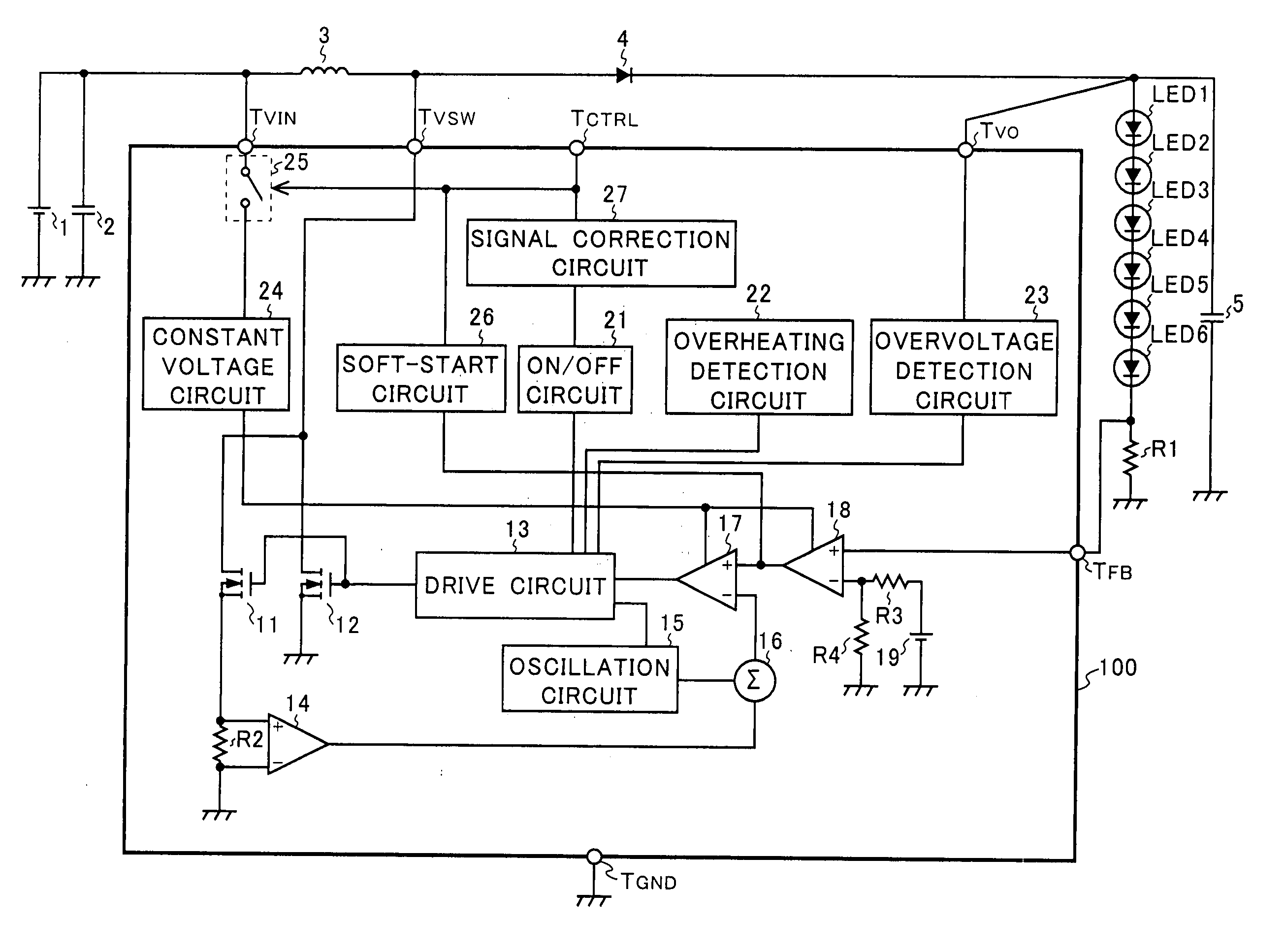
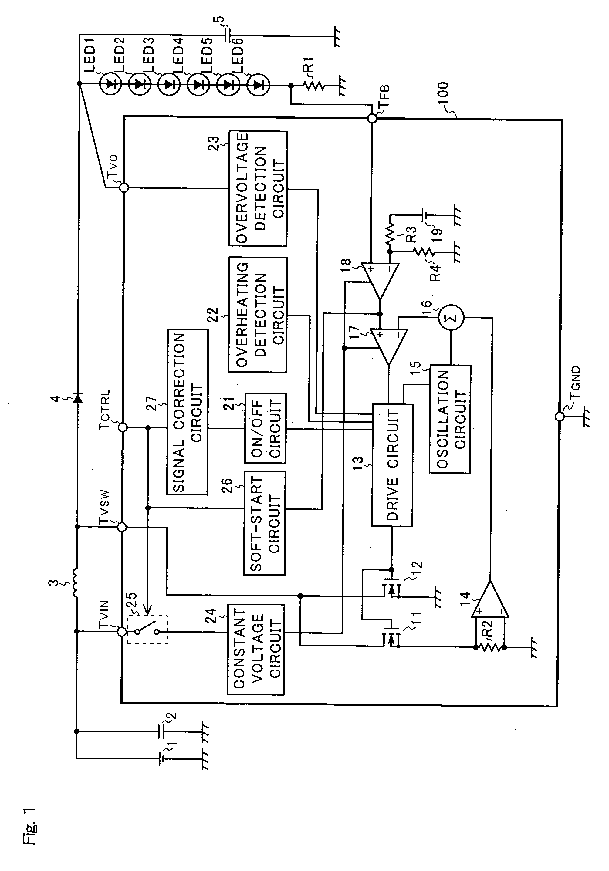
[0068] An example of the configuration of a switching power supply circuit embodying the invention is shown in FIG. 1. Note that, in FIG. 1, such members as are found also in FIG. 11A are identified with common reference numerals, and their detailed descriptions will be omitted.

[0069] The switching power supply circuit shown in FIG. 1 embodying the invention has a configuration in which the stepping-up chopper regulator 10 of the conventional switching power supply circuit shown in FIG. 11A is replaced with a stepping-up chopper regulator 100. The stepping-up chopper regulator 100 differs from the stepping-up chopper regulator 10 in that the soft-start circuit 20 of the stepping-up chopper regulator 10 is replaced with a soft-start circuit 26, and a signal correction circuit 27 that receives a brightness adjusting signal from the control terminal TCTRL and feeds to the on / off circuit 21 a corrected signal obtained by correcting the received brightness adjusting signal is additional...


PUM


Abstract

In a switching power supply circuit, completion of discharging of a capacitance provided in a soft-start circuit requires a period longer than a cycle with which an activating/deactivating portion switches switching control operation of a driving portion (which performs switching control to turn on/off a switching device provided in a stepping-up DC-DC converter) between an activated state and a deactivated state. Moreover, the soft-start circuit is prevented from performing soft-start operation until discharging of the capacitance is completed. Furthermore, the activating/deactivating portion prevents the switching control operation of the driving portion from being switched from the deactivated state to the activated state from a time point that constant voltage feeding operation of a constant voltage portion (which feeds, to a comparing portion that sends an output signal to the driving portion, a constant voltage as the drive voltage) is switched from the deactivated state to the activated state until a predetermined period elapses.

Description

[0001] This nonprovisional application claims priority under 35 U.S.C. § 119(a) on Patent Application No. 2004-299572 filed in Japan on Oct. 14, 2004, the entire contents of which are hereby incorporated by reference. BACKGROUND OF THE INVENTION [0002] 1. Field of the Invention [0003] The present invention relates to a switching power supply circuit that steps up the input voltage from a direct-current source and then feeds it to a load. More particularly, the present invention relates to a switching power supply circuit that activates / deactivates stepping-up operation according to an external signal. [0004] 2. Description of Related Art [0005] In recent years, white light-emitting diodes that are excellent in durability, luminous efficiency, and space-saving, etc., have come to be used as one of the illumination light sources (backlights or frontlights) of liquid crystal display devices (LCDs) incorporated in electronic apparatuses such as cellular phones, PDAs (personal digital as...

Claims


Application Information

Patent Timeline
IPC IPC(8): G05F1/618
CPCH02M1/32H02M1/36H02M3/156H02M2001/0006Y10S323/901H02M1/0006
Inventor WARITA, HIROHISAKANAMORI, ATSUSHIINABA, KATSUMISATOH, TSUTOMU
Owner SHARP KK
Why Eureka
Try Eureka