Recording method and optical disc apparatus

Inactive Publication Date: 2006-04-20
HITACHI LTD +1
View PDF14 Cites 46 Cited by
  • Summary
  • Abstract
  • Description
  • Claims
  • Application Information

AI Technical Summary

Benefits of technology

[0010] In the aforementioned examples of the test write procedure, the write power and pulse shape conditions are optimized upon loading of the disc into the drive unit in accordance with the condition of the disc and the drive unit. In the case of a disc such as the aforementioned DVD-RAM in which more than a hundred thousand rewrites are possible and which has a sector structure, the write conditions can be optimized by repeating a recording or reading a number of ti

Problems solved by technology

On the other hand, in disc media such as DVD-Rs which are recordable only once, it is difficult to calibrate the write pulse shape.
In such an environment surrounding the development of the drive units, tremendous amounts of work hours are spent on the selection of an appropriate write pulse shape condition for each of the huge numbers of optical disc media.
Actually, it is not too much to say that t

Method used


Image

  • Recording method and optical disc apparatus
  • Recording method and optical disc apparatus
  • Recording method and optical disc apparatus

Examples


embodiment 1

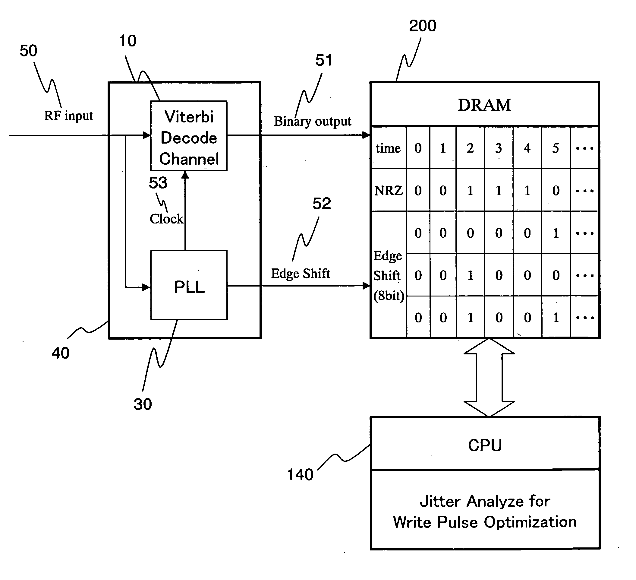
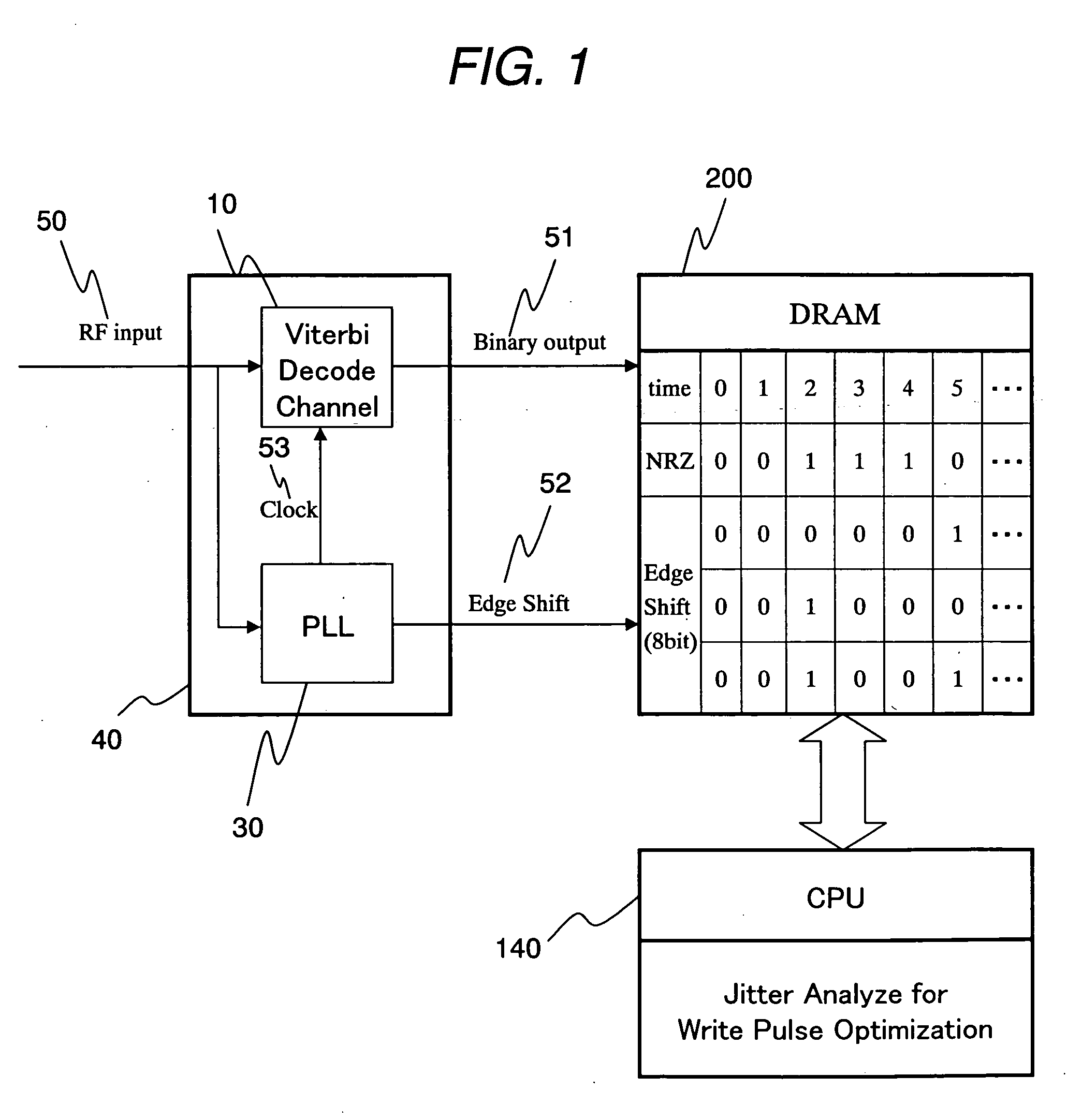
[0094] The block diagram of an apparatus in accordance with the invention will be described in detail. FIG. 11 shows the diagram of a circuit suitable for the write method and optical disc apparatus of the invention, showing the block shown in FIG. 1 in greater detail. The circuit generally consists of a read signal processing circuit 40, an external memory 200, and a CPU 140. The read signal processing circuit 40 comprises a Viterbi decoder unit 10, a PLL 30, and a delay unit 20. The Viterbi decoder unit 10 includes an analog equalizer 11, an A / D converter 12, an FIR (Finite Impulse Response) filter 13, and a PRML decoder 14. A read signal 50 read by an optical head (not shown) is equalized and low-pass filtered by the analog equalizer 11. The thus processed signal is then sampled by the A / D converter 12 at each clock and converted into a 6- to 8-bit digital data sequence. The digital data sequence is digitally equalized by the FIR filter 13 and then binarized by the PRML decoder 1...

case 1

(Case 1) Where the edge point is a sampling point.

[0105] Edge detection condition: y[i−1]×y[i+1][0106] Edge slope: m=(y[i−1]−y[i+1]) / 2 [0107] Edge point level: ye=y[i][0108] Edge shift amount: ES=−ye / m

(Case 2) Where the edge point is between two sampling points. [0109] Edge detection condition: y[i]×y[i+1][0110] Edge slope: m=y[i+1]−y[i][0111] Edge point level: ye=(y[i]+y[i+1]) / 2 [0112] Edge shift amount: ES=−ye / m

[0113] In Case 2, since the edge level is not sampled directly, the edge level is handled as a mean value of levels at two sampling points. Using these techniques, it becomes possible to basically measure the edge shift.

[0114] Whether the clock point is synchronized with an edge of a signal is basically determined by the target signal level of the PRML. The description of the relationship between the target signal level of PRML and the class bit number is omitted herein.

[0115]FIG. 14 shows another embodiment illustrating the structure of a circuit suitable for the writ...

embodiment 2

[0135] The foregoing has been the description of the structure of the circuit for implementing the invention and the structure of the analysis program. In the following, a technique (write method) for optimizing the write pulse shape and power is described in specific terms.

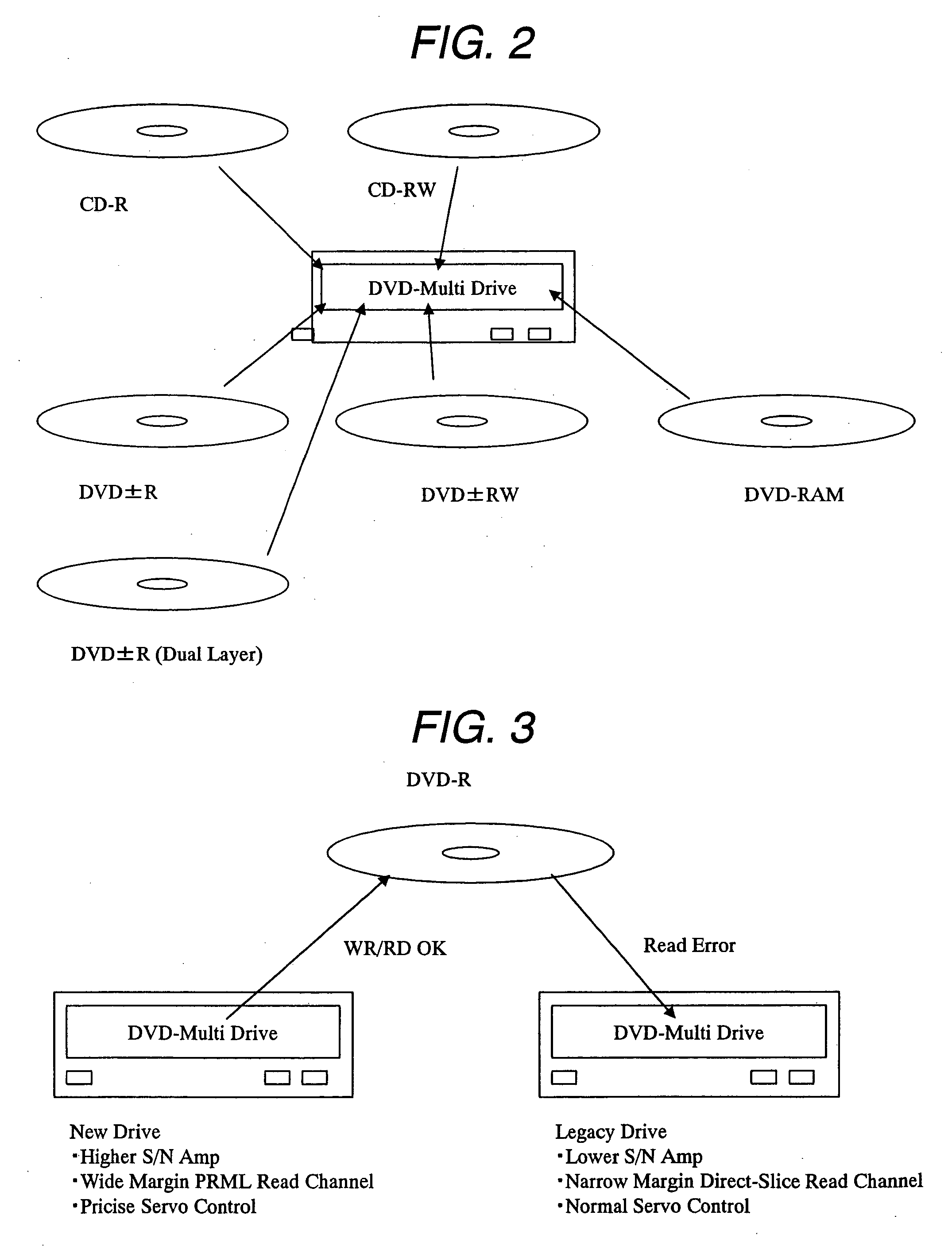
[0136] As the initial values for the write pulse shape and power, parameters recommended by the manufacturer of disc media are generally used. Individual parameters of the write strategy recommended by the disc media manufacturers are recorded in the control data region that is not rewritable, in the wobble signal in which address information is recorded, or in a part of the land pre-pit information. In the following, the difference in write pulse shapes among three kinds of disc media, namely, DVD-RAM, DVD-R, and DVD-RW, will be initially discussed.

[0137]FIG. 27 shows the contents of the write strategy data recorded in the control data section of the DVD-RAM. As shown, the 2×, 3×, and 5× DVD-RAM media that hav...


PUM


Abstract

In a recordable optical disc apparatus, the efficiency of the work necessary for optimizing the write pulse condition (write strategy) is improved and the read compatibility among drive units is ensured by a minimum addition of circuitry. An edge shift amount or a read signal and a binarized result are stored in an external memory as digital data and are later processed by analysis software in a host PC. The write pulse shape and power conditions can be optimized to individual optical disc media in a short time by means of a simple circuit. Further, by optimizing the write pulse shape and power condition in view of the PRML class or the difference in NA of the head, any deterioration of read compatibility can be avoided.

Description

CLAIM OF PRIORITY [0001] The present application claims priority from Japanese application JP 2004-305083 filed on Oct. 20, 2004, the content of which is hereby incorporated by reference into this application. BACKGROUND OF THE INVENTION [0002] 1. Field of the Invention [0003] The present invention relates to an optical disc recording method and apparatus for recording information by forming a recording mark on a recording medium whose physical properties are different from those of the other portions of the medium. [0004] 2. Description of Related Art [0005] Optical disc media such as DVD-RAM and DVD-RW that employ rewritable phase-change optical recording material are in widespread use. Recently, greater capacity Blu-ray Disc products that employ blue laser and that accommodate high-vision broadcast recording have also been put on the market. There is now a growing need for optical disc apparatuses capable of reading and writing DVDs and Blu-ray Discs on a single drive unit. When ...

Claims


Application Information

Patent Timeline
IPC IPC(8): G11B7/12
CPCG11B7/0062G11B7/1267G11B20/10009G11B20/10046G11B20/10055G11B20/10166G11B20/10222G11B20/10296G11B20/10481G11B2007/0006G11B7/004G11B7/0045
Inventor MINEMURA, HIROYUKI
Owner HITACHI LTD
Why Eureka
Try Eureka