Film deposition apparatus and film deposition method

a film deposition apparatus and film technology, applied in the field of film deposition apparatus and film deposition method, can solve the problem that the characteristics of arc heating method allowing film deposition at high rate cannot be fully taken advantage, and achieve the effect of stable shap

Inactive Publication Date: 2006-04-20
CANON KK
View PDF16 Cites 0 Cited by
  • Summary
  • Abstract
  • Description
  • Claims
  • Application Information

AI Technical Summary

Benefits of technology

[0026] The present invention is proposed to solve the above problems, and an object thereof is to provide a film deposition apparatus and a film deposition method for forming particles by arc heating. With the film deposition apparatus and method, the resulting particles can be efficiently sucked up into a transfer tube regardless of an arc voltage, and the resulting film can be stable in shape.
[0041] In the present invention, each sub electrodes are arranged at mutually different direction with respect to a material. In an exemplary structure, the sub electrodes are arranged so that the material is surrounded, and a vector sum of thermionic current from the tips of the sub electrodes (discharge sections) is directed to any one specific part of the material (preferable if directed in the vertical direction of the material surface). With such a structure, no matter what arc voltage is to be applied, the ultra-fine particle smoke (particle flow) generated by arc discharge is not blown off into a wrong direction but efficiently sucked up into a transfer tube with the carrier gas flow coming from the bottom part of the evaporation source. Further, the particle smoke becomes easier to be sucked up into the center of the suction part of the transfer tube. Accordingly, the resulting film can be stable in shape, and the cross section thereof is thicker in the center.

Problems solved by technology

The above conventional technology, however, carries the following problems.
Consequently, the characteristics of arc heating method allowing film deposition at high rate cannot be fully taken advantage of.

Method used


Image

  • Film deposition apparatus and film deposition method
  • Film deposition apparatus and film deposition method
  • Film deposition apparatus and film deposition method

Examples


example 1

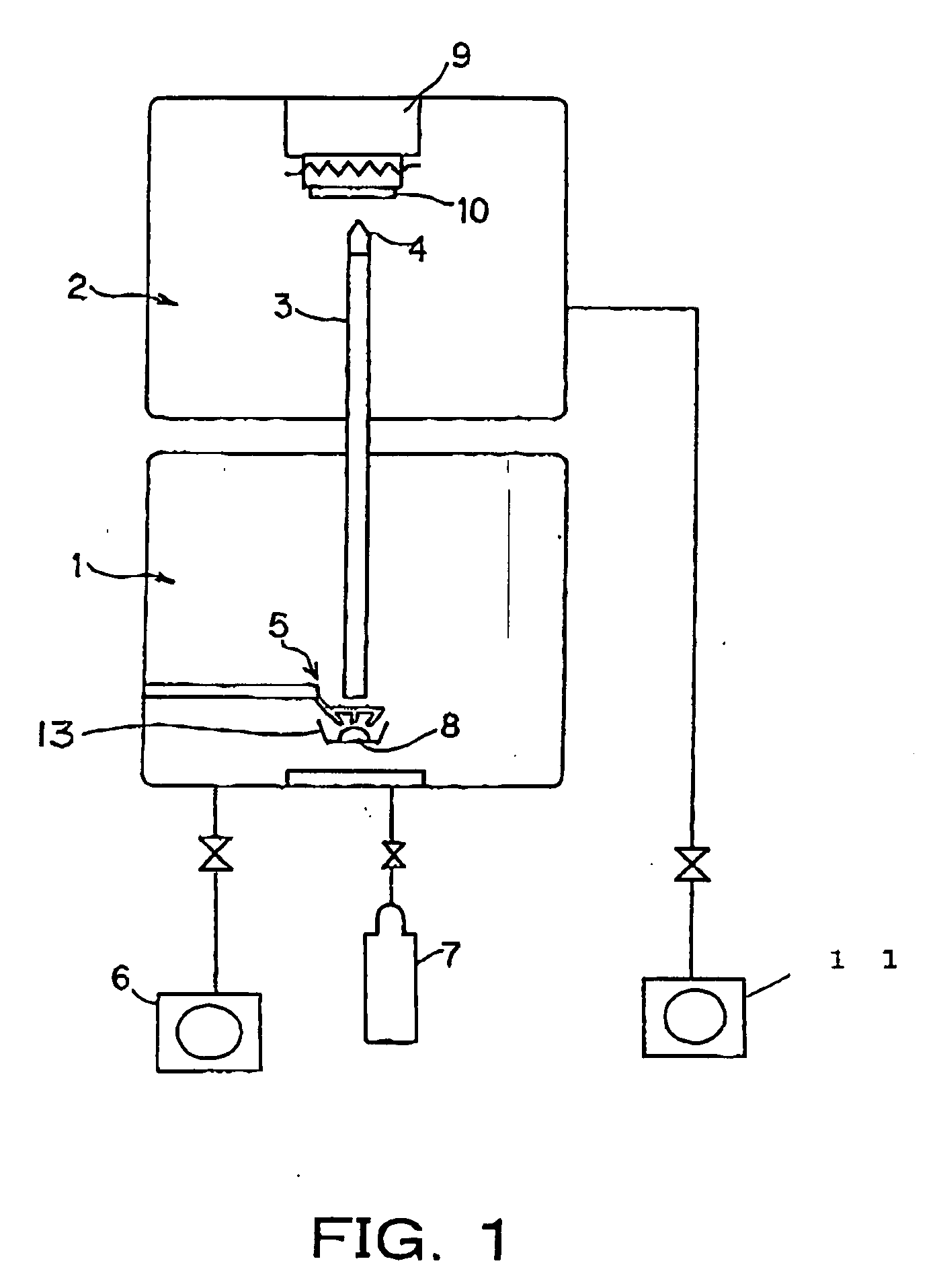
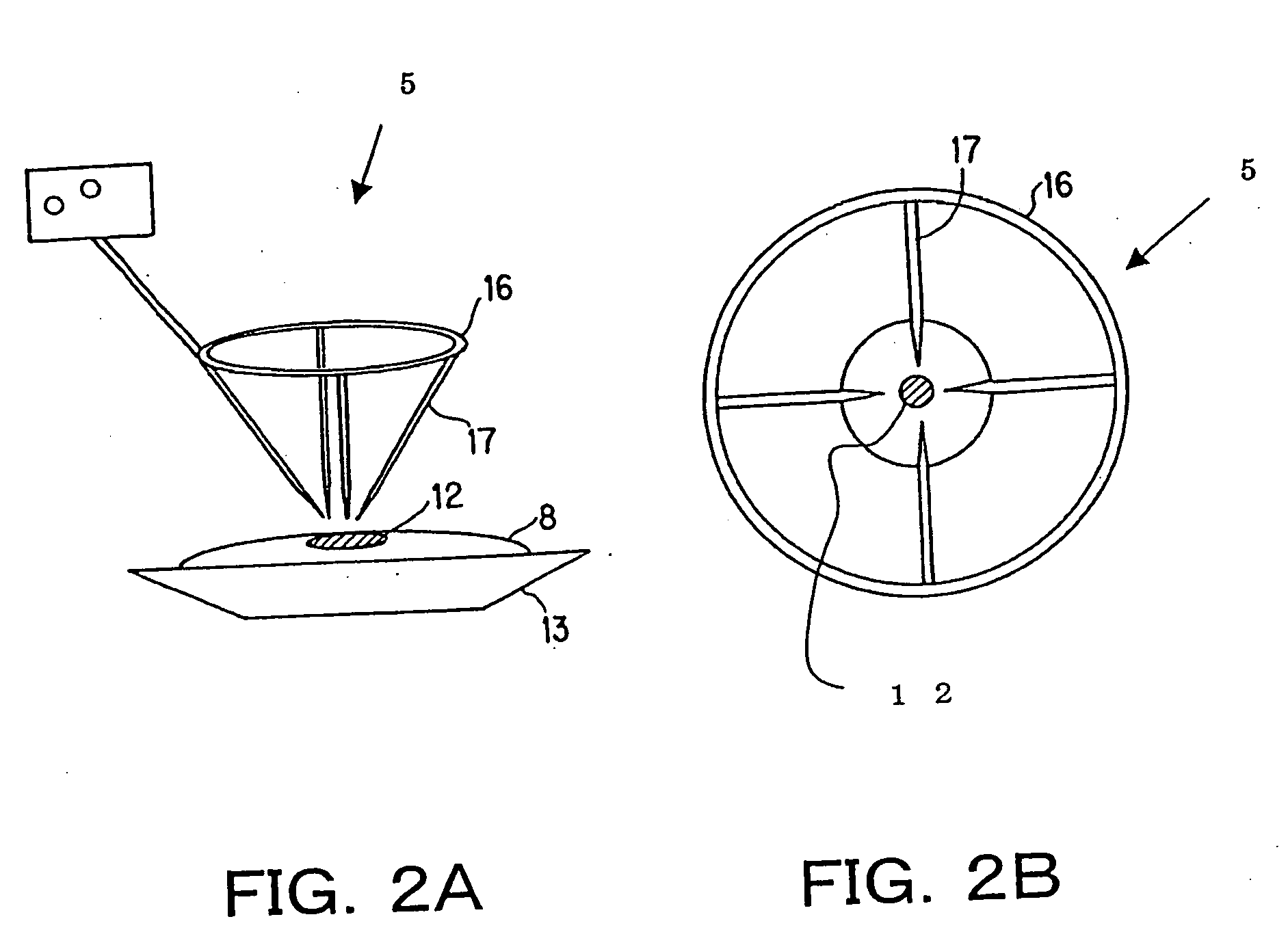
[0060]FIGS. 2A and 2B are both schematic diagrams showing the arc heating electrode 5 of the Example 1. The arc heating electrode 5 of Example 1 is configured by four sub electrodes (rod electrodes) 17. FIG. 2A is a perspective view, and FIG. 2B is a plan view. The general construction of the film deposition apparatus is equivalent to that schematically shown in FIG. 1.

[0061] As shown in FIGS. 2A and 2B, in this example, to use as the arc heating electrode (first electrode) 5 has a circular tungsten-made ring 16 with four 1 mm-diameter tungsten-made rods (sub electrodes) 17 fixed thereon. The tungsten-made rods 17 are so arranged that the tips thereof each form, lengthwise, an angle of approximately 45 degrees with respect to the vertical direction of the surface of the material 8. Further, the rods 17 are fixed on the circular tungsten-made ring 16 using screws so that the rod tips direct to the melting part 12 of the material 8. In this example, with such an arc heating electrode...

example 2

[0078]FIGS. 3A and 3B are both schematic diagrams showing the first electrode (arc discharge electrode) 5 of this example, more specifically, showing the first electrode 5 configured by eight sub electrodes 19. FIG. 3A is a perspective view, and FIG. 3B is a plan view. The general construction of the film deposition apparatus in its entirety is equivalent to the one schematically shown in FIG. 1.

[0079] As shown in FIGS. 3A and 3B, in this example, an octangle molybdenum-made jig 18 is provided with eight holes, at equal intervals, to allow 1 mm-diameter rod electrodes (sub electrodes) 19 to pass therethrough. As the rod electrodes 19, used are 1 mm-diameter eight tungsten-made rods 19 to which yttrium oxide (Y2O3) is doped. Here, the rod electrodes 19 are so arranged that the tips thereof each form, lengthwise, an angle of approximately 45 degrees with respect to the vertical direction of the surface of the material 8. Further, to have the rod tips direct to the melting part 12 of ...

example 3

[0096]FIGS. 4A to 4D are all schematic diagrams showing the arc heating electrode (first electrode) 5 of this example. In this example, three rod electrodes 21 are used as the sub-electrodes. FIG. 4A is a perspective view, FIG. 4B is a plan view, FIG. 4C is a perspective view of a rod electrode 21, and FIG. 4D is a plan view of the rod electrode 21. The general construction of the film deposition apparatus is equivalent to the one schematically shown in FIG. 1.

[0097] In this example, the sub-electrode configured by three carbon rods 21 is used to produce a mirror out of ultra fine Al particles.

[0098] The carbon rod 21 is 1 mm in diameter. As shown in FIG. 4C, two of the three rod electrodes 21 are so fixed as to form an angle of 30 degrees with respect to the vertical direction of the surface of the material 8. The remaining one electrode is so fixed as to form an angle of 45 degrees with respect to the vertical direction of the surface of the material 8. The angles between the ro...


PUM

PropertyMeasurementUnit
angleaaaaaaaaaa
Pressureaaaaaaaaaa
voltageaaaaaaaaaa

Abstract

A particle film deposition apparatus and method are provided, with which ultra fine particles are generated by arc heating. The generated ultra fine particles can be efficiently sucked up into a transfer tube regardless of an arc voltage, and the resulting film can be stable in shape. An evaporation material 8 to be evaporated by arc heating and to generate ultra fine particles is connected to an electrode. As other electrodes, a plurality of rods 17 each having a discharge section at the tip thereof are provided. These rods 17 are so arranged as to be directed in each different direction with respect to the evaporation material 8.

Description

[0001] This application claims the right of priority under 35 U.S.C. §119 based on Japanese Patent Application Nos. JP 2002-122314 filed on Apr. 24, 2002 and JP2003-117358 filed on Apr. 22, 2003 which are hereby incorporated by reference herein their entirety as if fully set forth herein. BACKGROUND OF THE INVENTION [0002] 1. Field of the Invention [0003] The present invention relates to a film deposition apparatus and a film deposition method using ultra fine particles formed by arc heating method. [0004] 2. Description of the Related Art [0005] Conventionally, the film deposition apparatus of the above type is exemplified by the one having gas deposition method applied thereto. [0006] Such a gas deposition apparatus is structured by, for example, a ultra-fine particle generation chamber, a film deposition chamber, and a transfer tube for connection between the ultra-fine particle generation chamber and the film deposition chamber. In the ultra-fine particle generation chamber, arc...

Claims


Application Information

Patent Timeline
Patent Type & Authority Applications(United States)
IPC IPC(8): C23C14/00C23C16/00H05H1/48B01J19/08C23C14/24C23C14/32H05H1/24
CPCC23C14/228C23C14/325H05H1/24H05H1/48H05H1/471H05H2245/50C23C14/24
Inventor ISHIKURA, JUNRIKAMEYAMA, MAKOTOSAITO, YASUYUKI
Owner CANON KK
Why Eureka
Try Eureka