Instrument and method for the insertion and alignment of an intervertebral implant

a technology of intervertebral implants and instruments, which is applied in the field of instruments and methods for the insertion and alignment of intervertebral implants, can solve the problems of difficult interoperative process and injury to patients, and achieve the effects of reducing the likelihood of implant expulsion, and reducing the wear of the implan

Active Publication Date: 2006-04-20
DEPUY SPINE INC (US)
View PDF35 Cites 336 Cited by
  • Summary
  • Abstract
  • Description
  • Claims
  • Application Information

AI Technical Summary

Benefits of technology

[0011] By practicing the present invention, pins can be placed midline (lateral / medial) to the spine of a patient. Furthermore, midline placement of the pins in adjacent vertebrae using the present invention can be more reliable and reproducible than present methods for placing pins in adjacent vertebrae. Practice of the present invention also provides reliably correct alignment of pins in adjacent vertebrae. For example, practice of the invention can provide substantial parallel alignment of pins placed in adjacent vertebrae. The present invention can also produce parallel alignment of pins with the endplates of the vertebrae in which the pins are placed.
[0012] Through practice of the present invention, correctly aligned pins can be placed into vertebrae using the pin guide using the relatively easy and reliable methods described herein. Practice of the present invention can also provide anterior / posterior sizing information and superior / inferior sizing information for an intervertebral implant subsequently inserted into the intervertebral space.
[0019] Despite existing tools and techniques, present insertion and alignment of an intervertebral implant within an intervertebral space, like the placement of pins, described supra, often depends on a surgeon's skill, experience and technique. Practice of the present invention can aide in the insertion and alignment of intervertebral implants within an intervertebral space, e.g., midline to the coronal plane of the spine and parallel to the endplates of the vertebrae that abut the intervertebral space. Practice of the present invention is suitable for, for example, the insertion and alignment of implants typically used in disc replacement surgery or in spinal fusion surgery. By practicing the present invention, a surgeon can properly position an implant into an intervertebral space. Among other advantages, proper positioning of an intervertebral implant can reduce stresses on the facets, can reduce the likelihood of implant expulsion, can provide proper kinematics for the implant and spine, and can reduce wear of the implant. Furthermore, the methods and instruments described herein can be used to consistently position an implant within the intervertebral space.

Problems solved by technology

Spinal surgery involves many challenges as the long-term health and mobility of the patient often depends on the surgeon's technique and precision.
This process can present the surgeon with several challenges.
However, if the vertebral bodies are separated, or distracted, beyond a certain degree, injury to the patient can occur.
In some instances, the procedure may include trial and error to gain a desired pin position and alignment.
Proper insertion and alignment of an intervertebral implant can be of great importance, but unfortunately, this process can be challenging interoperatively and the specific placement of implants can vary from one surgeon to the next.

Method used


Image

  • Instrument and method for the insertion and alignment of an intervertebral implant
  • Instrument and method for the insertion and alignment of an intervertebral implant
  • Instrument and method for the insertion and alignment of an intervertebral implant

Examples


Embodiment Construction

[0049] The foregoing and other objects, features and advantages of the invention will be apparent from the following more particular description of preferred embodiments of the invention, as illustrated in the accompanying drawings in which like reference characters refer to the same parts throughout the different views. The drawings are not necessarily to scale, emphasis instead being placed upon illustrating the principles of the invention.

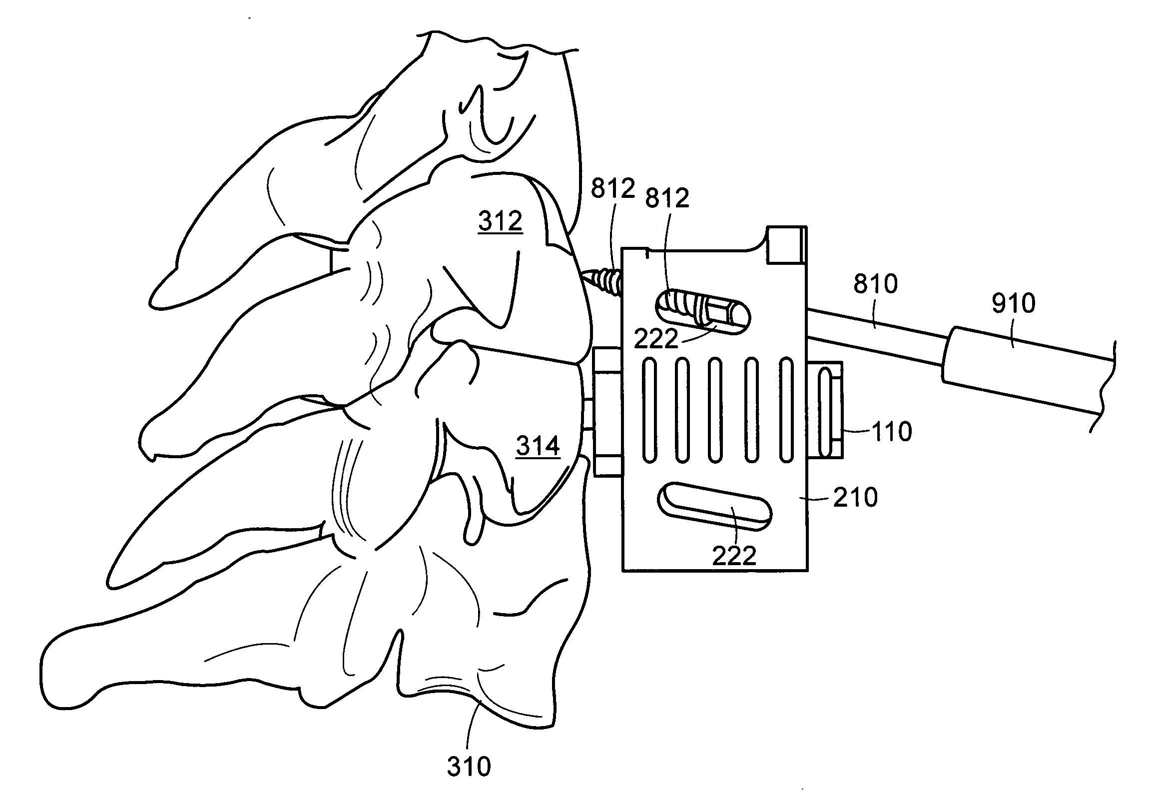
[0050] The present invention includes pin guides and methods for placing pins in adjacent vertebrae. The term “pin,” as used herein, refers to a pin (e.g., a threaded or partially threaded pin) or screw suitable for use in spine surgical procedures. For example, pins suitable for use with the present invention include distraction pins.

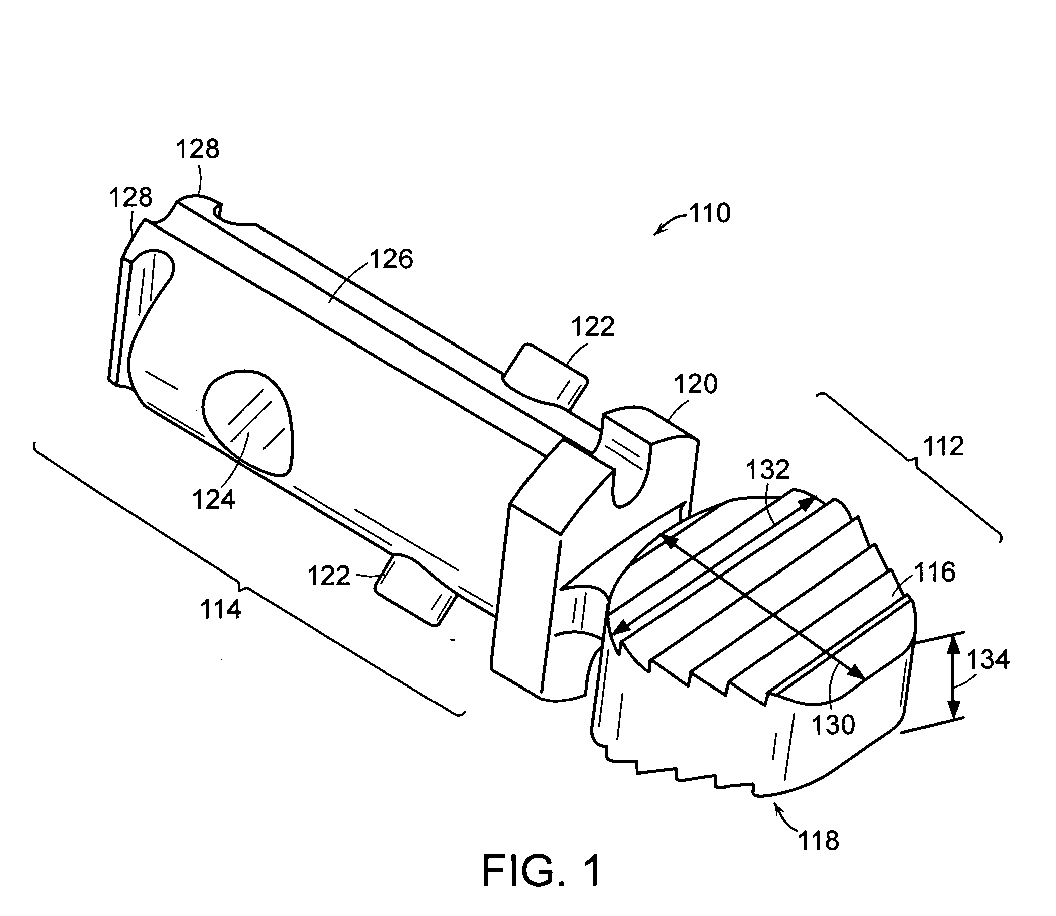
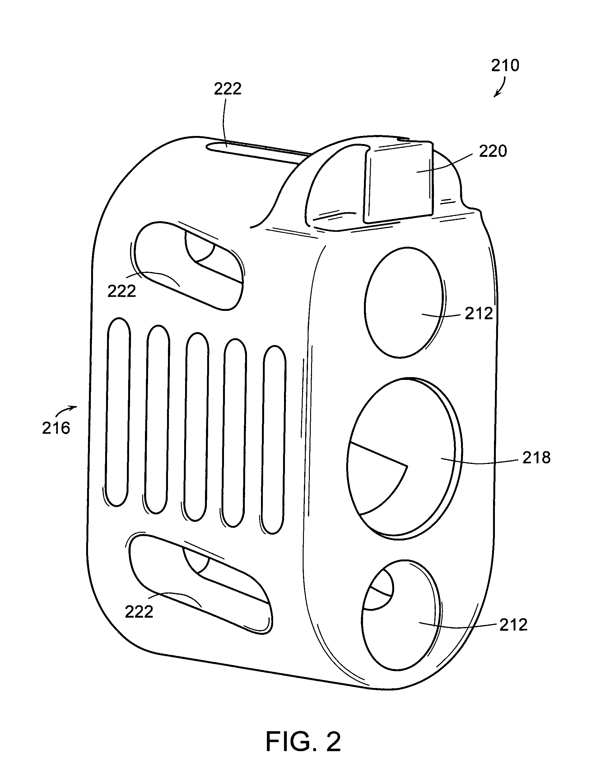
[0051] The present invention includes a modular pin guide comprising (a) a spacer component including an intervertebral spacer and a coupling member; and (b) a guide component defining a plurality of parallel gui...


PUM


Abstract

The present invention includes pin guides and methods for placing pins in adjacent vertebrae. The present invention also includes methods for placing pins in adjacent vertebrae using the pin guides described herein. The present invention also includes an intervertebral implant insertion and alignment instrument, a distraction instrument, an intervertebral implant insertion guide, and methods for inserting an implant into an intervertebral space. Despite existing tools and techniques, present positioning of implants in intervertebral spaces and pins in adjacent vertebrae often depend on a surgeon's skill, experience and technique. Practice of the present invention can aide in the placement of an implant into an intervertebral space and placement of pins in adjacent vertebrae, e.g., midline to the coronal plane spine and / or parallel to vertebral endplates that abut the intervertebral space.

Description

RELATED APPLICATION [0001] This application claims the benefit of U.S. Provisional Application No. 60 / 615,544, filed Sep. 30, 2004, under Attorney Docket No. 3518.1026-000, the entire teachings of which are incorporated herein by reference.BACKGROUND OF THE INVENTION [0002] Spinal surgery involves many challenges as the long-term health and mobility of the patient often depends on the surgeon's technique and precision. One type of spinal surgery involves the removal of an existing intervertebral disc located between adjacent vertebral bodies. Procedures are known in which an existing intervertebral disc, for example, natural damaged disc tissue, is replaced with a disc prosthesis or with an interbody cage or fusion device. Replacement of a vertebral disc can include removing an existing intervertebral disc or portion of an intervertebral disc, distracting apart vertebral bodies, and inserting a replacement intervertebral disc into the intervertebral space. [0003] This process can pr...

Claims


Application Information

Patent Timeline
Patent Type & Authority Applications(United States)
IPC IPC(8): A61F2/30
CPCA61B17/025A61B17/1735A61B17/1757A61B2017/0256A61F2/442A61F2/4611A61F2/4684A61F2002/30235A61F2002/4627A61F2002/4628A61F2230/0069A61F2002/4687A61B17/7077
Inventor GRINBERG, ALEXANDERMCGITTIGAN, WILLIAMZALENSKI, EDWARD B.GARNER, RONALDBURKE, ANDREA
Owner DEPUY SPINE INC (US)
Why Eureka
Try Eureka