Method of producing resin joint boot

a technology of resin and joint, applied in the direction of electrical/magnetic/electromagnetic heating, couplings, other domestic articles, etc., can solve the problem of not being able to conduct laser irradiation circumferentially, and achieve the effect of reducing overall production cost, increasing production steps, and high molding precision

Inactive Publication Date: 2006-04-27
TOYO TIRE & RUBBER CO LTD
View PDF4 Cites 9 Cited by
  • Summary
  • Abstract
  • Description
  • Claims
  • Application Information

AI Technical Summary

Benefits of technology

[0013] According to this invention thus constituted, because of the fact that the bushing having on its internal periphery the convex portions to be received in a plurality of the concave portions on the external periphery of the outer casing is molded separately from the boot body and after molding, both are integrated by laser welding, the invention method dispenses with the use of a special mold for molding of both as compared to the case where both are integrally molded from the outset, although the number of the production steps is increased; the time required for laser welding is shorter than the molding cycle time in the case of integral molding; the production of sinks ascribed to shrinkage after molding is very low and hence, a high molding precision and any configurational improvement for coping with the production of sinks are not required. Taken altogether, these enable the overall production cost to be reduced and a good sealing capability between the bushing and the outer casing to be ensured.
[0014] Further because the boot body and the bushing are integrally joined together by laser welding, it is possible to ensure sufficiently the durability of the overall joint boot made of resin while holding an equal integrity to an integrally molded product of both, without the bushing being disengaged or being loose when the joint boot is installed and used.
[0015] Again because the outwardly diverging tilting surface is provided on the internal peripheral face of the boot body while the bushing is provided with the annular projecting portion to be abuttingly disposed on the tilting surface, and laser beam is irradiated penetrating through the annular projecting portion onto the tilting surface, the laser irradiation angle to the biting surface, when laser beam is irradiated obliquely from above the center axis (tuber axis line) at the location axially spaced apart from the boot body, can be made perpendicular or nearly perpendicular. As a consequence, an efficient laser welding can be conducted in spite of the fact that the bushing has on its internal periphery the convex portions. Stated another way, it is possible to ensure good welding performance while minimizing the intensity of laser beam to suppress an increase in consumption power as far as possible.
[0016] In the manufacturing method of this invention, the aforesaid annular projecting portion is provided with a welding surface to be abuttingly disposed on the biting surface and a laser incidence surface on which laser is incident, and the thickness of the annular projecting portion defined by the distance between the welding surface and the incident surface is preferred to be constant. In this manner the thickness of the annular projecting portion through which laser penetrates is made constant, whereby it is possible to make the optical path length of the laser beam penetrating through the annular projecting portion constant, even if the laser irradiating position is deviated owing to an error caused when the boot body is installed on a laser irradiation equipment, thus avoiding an incomplete welding.

Problems solved by technology

However, since the bushing has the convex portions on the internal peripheral part as mentioned above, upon irradiation of laser beam if the laser radiation is directed radially outwardly from a center position of the bushing, a difference in optical path lengths of laser transmitted through the resin material portion of the bushing is created between a location with the convex portions and a location without them, as a result of which it is unable to conduct the laser irradiation with a circumferentially even energy.

Method used


Image

  • Method of producing resin joint boot
  • Method of producing resin joint boot
  • Method of producing resin joint boot

Examples


Embodiment Construction

[0026] Embodiments for carrying out the invention will be hereinafter described with reference to the accompanying drawings.

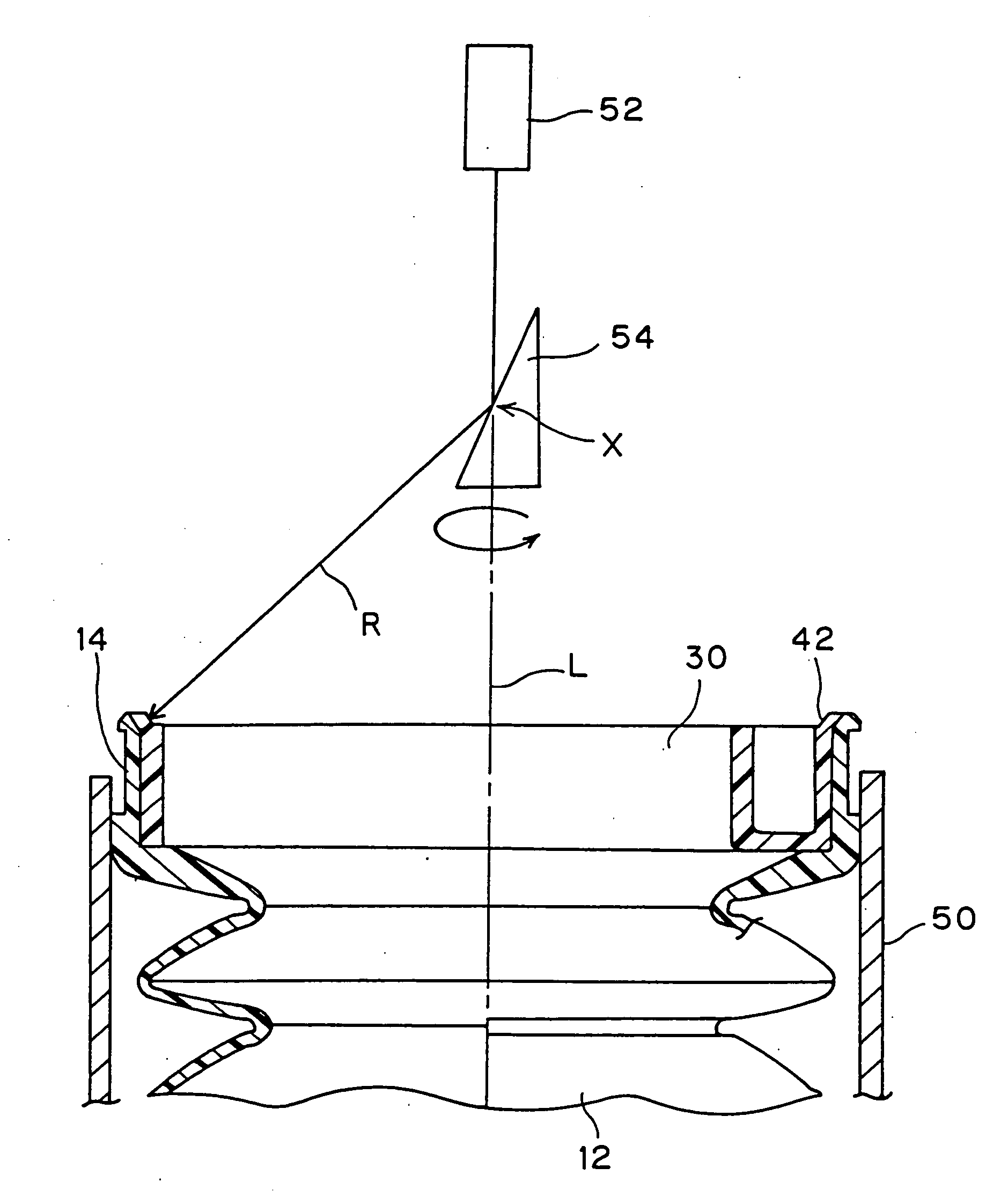
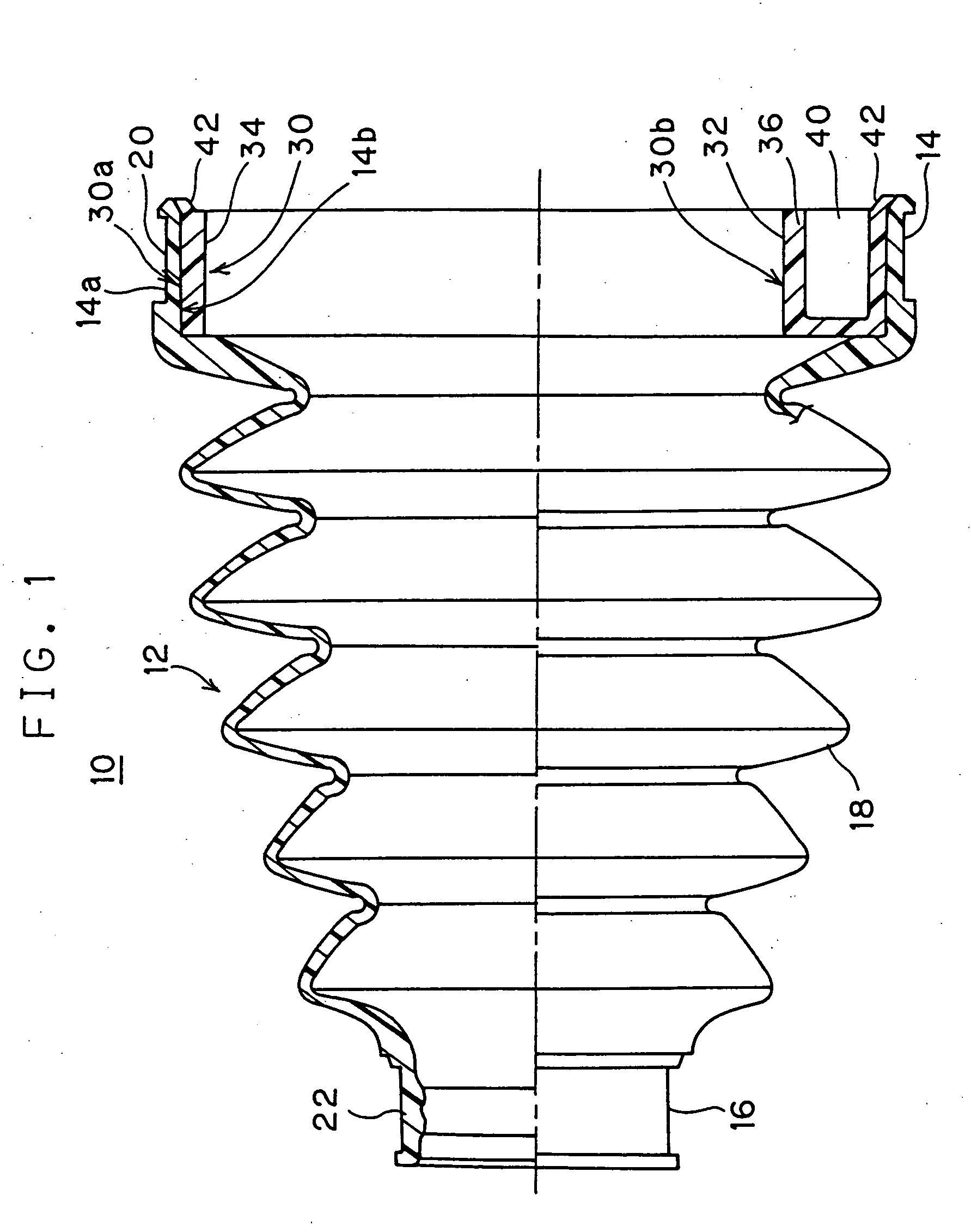
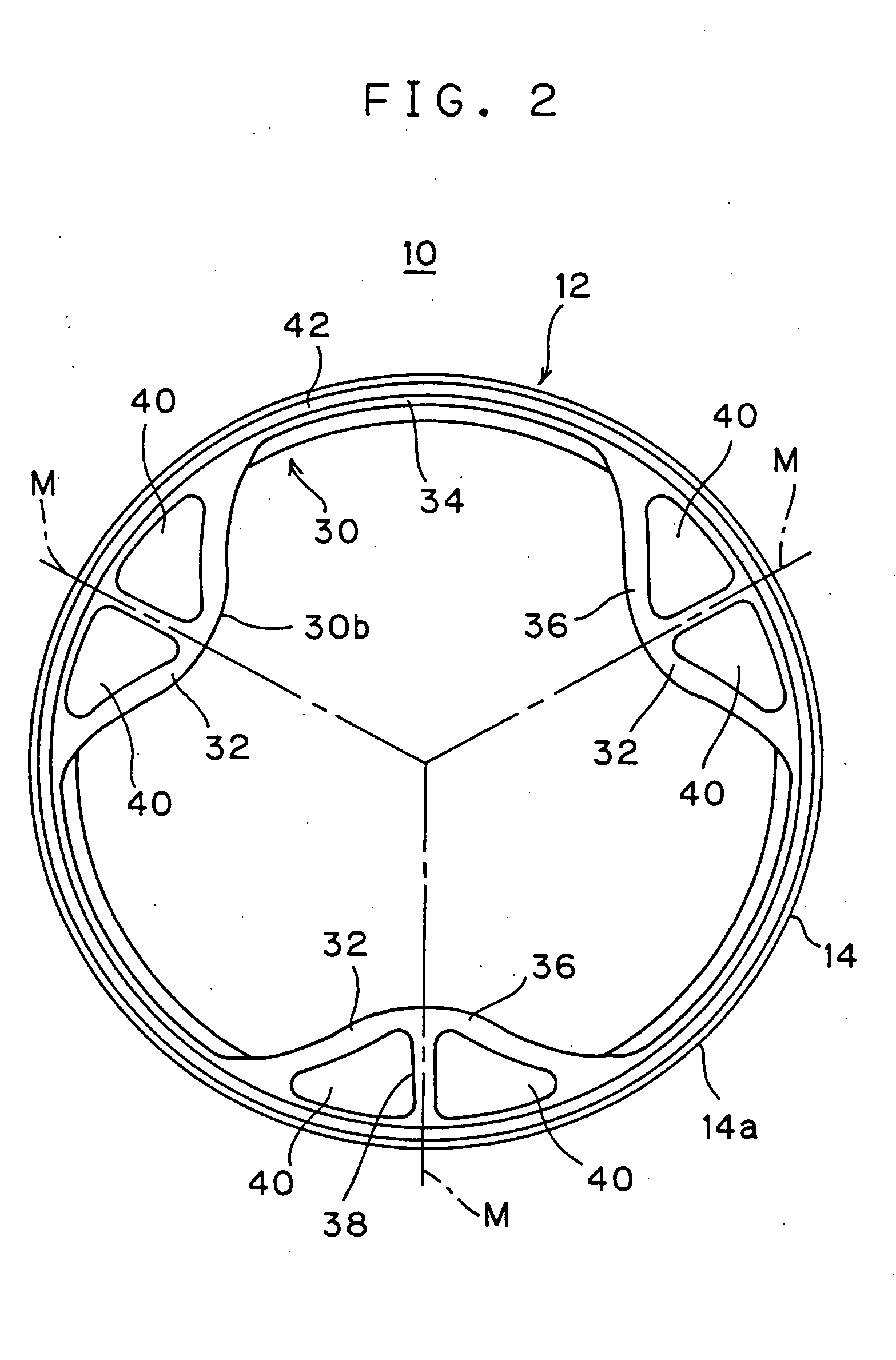
[0027] A resin-made joint boot 10 relating to this embodiment as shown in FIGS. 1 and 2 is destined to be installed on a tripod type of constant velocity joint for automobiles illustrated in FIGS. 6 and 7 and comprises a boot body 12 and a bushing 30 integrally joined.

[0028] The boot body 12 includes a large-diameter tubular part 14 on an axially one end side, a small-diameter tubular part 16 on the other end side disposed coaxially in a spaced relation to the large-diameter tubular part 14, and a bellows part 18 interconnecting the large-diameter tubular part 14 and the small-diameter tubular part 16. The large-diameter tubular part 14 assumes the form of a short cylinder to be externally fitted and secured on an outer casing 6, with the bushing 30 interposed as an insert material and is provided, on its external peripheral surface, with a circumferentially ...


PUM

PropertyMeasurementUnit
energy absorbingaaaaaaaaaa
diameteraaaaaaaaaa
thicknessaaaaaaaaaa

Abstract

A method of manufacturing a resin-made joint boot (10) provided with a boot body (12) including a large-diameter tubular part (14), a small-diameter tubular part (16) and a bellows section (18), and a bushing (30) fitted inside the large-diameter tubular part, wherein the boot body and the bushing are separately molded, the bushing is positioned inside the large-diameter tubular part of the boot body, and then, both are integrally fastened by laser welding. The large-diameter tubular part (14) is provided on its internal periphery with an outwardly divergent tilting surface (24) while the bushing (30) is provided with an annular projecting portion (42) to be abuttingly disposed on the tilting surface, and laser (R) is irradiated, penetrating through the annular projecting portion (42) onto the tilting surface (24).

Description

TECHNICAL FIELD [0001] This invention relates to a resin-made joint boot in a bellows form, for example, used for covering parts of shafts of an automotive constant velocity joint, and more particularly to the production of the resin-made joint boot suitable for a tripod type joint part adopted for constant velocity joints for automotive drive shafts or the like. BACKGROUND ART [0002] A constant velocity joint of this tripod type comprises, as shown in FIGS. 6 and 7, a tripod member 4 constructed so that three trunnions 3 each supporting and bearing rotatably a roller 2 protrude in a normal direction to the axis of the one shaft 1 of an input shaft and an output shaft, and an outer casing 6 connected to an end of the other shaft 5. The outer casing 6 is provided on its inner periphery with three axially extending slide grooves 6a that correspond to the three rollers 2 of the tripod member 4. The constant velocity joint is constructed so that the three rollers 2 of the tripod member ...

Claims


Application Information

Patent Timeline
Patent Type & Authority Applications(United States)
IPC IPC(8): B32B37/00H05B6/00B29C65/00B29C65/16F16D3/205F16D3/84
CPCB29C65/1635B29C66/13B29C66/5344B29C66/612B29C66/65B29K2101/12B29L2016/00B29L2023/18B29L2031/703B29L2031/748F16D3/2055F16D3/845B29C65/00B29C65/1629B29C65/1654B29C65/1677B29C66/1122B29C66/1222B29C66/1226B29C66/12821B29C66/1286B29C66/1312B29C66/73921
Inventor OHSHITA, TAKENORIIMAZU, EIICHIUEDA, TAKESHISAITO, KATSUSHI
Owner TOYO TIRE & RUBBER CO LTD
Why Eureka
Try Eureka