Transmit-rake apparatus in communication systems and associated methods

a technology of communication system and signal-to-noise ratio, which is applied in the direction of transmission, electrical apparatus, etc., can solve the problems of occupying more physical space, brute force technique, and components with high power-handling capability usually cost more, so as to and improve the signal-to-noise ratio.

Inactive Publication Date: 2006-04-27
ALEREON
View PDF26 Cites 130 Cited by
  • Summary
  • Abstract
  • Description
  • Claims
  • Application Information

AI Technical Summary

Benefits of technology

[0009] The disclosed novel transmit-rake apparatus overcomes the disadvantages associated with improving the signal-to-noise ratio in communication systems. An improved signal-to-noise ratio would allow transmission of information at higher speed, through higher interference, or to receivers at longer distances.
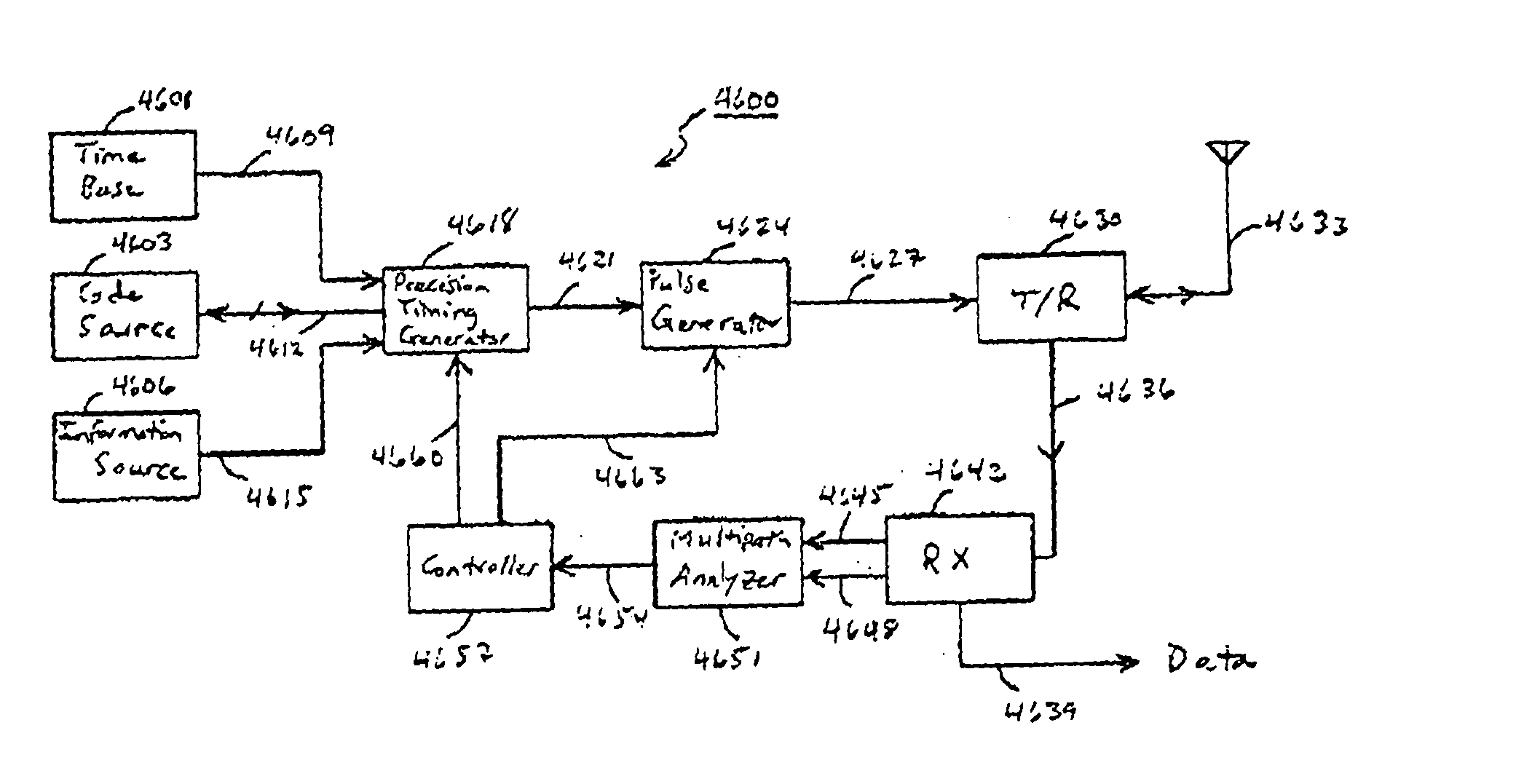
[0010] The transmit-rake apparatus according to the invention can improve the signal-to-noise ratio in a communication system without increasing the transmitted output RF power. It achieves that result by providing to a receiver a plurality of transmitted pulses that have individually selected timing and amplitudes. To achieve an even higher improvement in the signal-to-noise ratio, the transmit-rake apparatus according to the invention may individually select the polarity, as well as the timing and amplitude, of each of the plurality of pulses. The transmit-rake apparatus according to the invention preferably operates in ultra-wideband (also known as time-domain or impulse radio) communication systems that employ ultra-wideband signals.

Problems solved by technology

Unfortunately, that brute force technique has several drawbacks.
Components with high power-handling capability usually cost more and occupy more physical space.
Using those components therefore results in more costly and more bulky communication systems.
Second, increasing the transmitter's power arbitrarily may produce undesired interference with other equipment.
For example, increased transmitter power may interfere with medical instruments or sensitive communication equipment.
Third, increasing the transmitted power may pose health hazards.
Although the results to date seem inconclusive, some studies have shown that the relatively high RF levels of a cellular telephone may pose health risks for the telephone's user.
Fourth, increasing the transmitted power may be undesirable or even hazardous in some applications.
Finally, in some applications, one may not arbitrarily increase the transmitter's RF output power because of regulatory requirements.

Method used


Image

  • Transmit-rake apparatus in communication systems and associated methods
  • Transmit-rake apparatus in communication systems and associated methods
  • Transmit-rake apparatus in communication systems and associated methods

Examples


first embodiment

[0289] In a first embodiment, the signal strength of the received signal is used as a performance measurement. The power control update, dP, is given by:

dP=K(Pref−PS1) [0290] where K is a gain constant; [0291] PS1 is the signal strength of received signal S1; [0292] Pref is a signal strength reference; and [0293] dP is the power control update (which is preferable in the unit of Volts).

[0294] The output level of transmitter 602A (of transceiver 902A) is therefore increased when PS1 falls below Pref, and decreased when PS1 rises above Pref. The magnitude of the update is linearly proportional to the difference between these two signals. Note that the power control update can be equivalently expressed as an absolute rather than a differential value. This can be achieved by accumulating the differential values dP and communicating the resulting output level P as follows:

Pn=Pn-1+dP, [0295] Where Pn is the output level (e.g., voltage level or power level) to be transmitted during the n...

second embodiment

[0307] In a second embodiment, the SNR of the received signal is used as a performance measurement. The power control update, dP, is given by:

dP=K(SNRref−SNRS1) [0308] where K is a gain constant; [0309] SNRS1 is the signal-to-noise ratio of received signal S1; and [0310] SNRref is a signal-to-noise ratio reference.

[0311] The power of transmitter 602A (of transceiver 902A) is therefore increased when SNRS1 falls below SNRref, and decreased when SNRS1 rises above SNRref. The magnitude of the update is linearly proportional to the difference between these two signals. Note that the power control update can be equivalently expressed as an absolute rather than a differential value. As described above, those skilled in the art will recognize that many alternative equivalent formulations are possible for calculating a power control update according to received signal SNR.

[0312] A control loop diagram illustrating the functionality of this embodiment will now be described with reference t...

third embodiment

[0315] In a third embodiment, the BER of the received signal is used as a performance measurement. The power control update, dP, is given by:

dP=K(BERS1−BERref) [0316] where K is a gain constant; [0317] BERS1 is the bit error rate of received signal S1; and [0318] BERref is a bit error rate reference.

[0319] Note that the sign is reversed in this case because the performance indicator, BER is reverse sensed, i.e., a high BER implies a weak signal. The power of transmitter 602A (of transceiver 902A) is therefore decreased when BERS1 falls below BERref, and increased when BERS1 rises above BERref. The magnitude of the update is linearly proportional to the difference between these two signals. Note that the power control update can be equivalently expressed as an absolute rather than a differential value. As described above, many alternative formulations are possible for calculating a power control update according to received signal BER.

[0320] Note that BER measurements span a large ...


PUM


Abstract

A transmit-rake apparatus includes at least one pulse generator that provides a plurality of pulses with selected signal properties so as to improve the signal-to-noise ratio at a receiver. The signal properties may include pulse timing, amplitude, polarity, and pulse shape. The transmit-rake apparatus may use a multipath analyzer, receive multipath or signal-quality information, or use a combination of those techniques. The multipath analyzer may include a scanning receiver to generate a scan of the multipath response. Correlation of the multipath response with a model pulse shape may be used to establish pulse position and amplitude. Iteration based on link performance measurements may be used to select or refine pulse properties. A method is disclosed to vary the selection of pulses to improve the spectrum.

Description

TECHNICAL FIELD OF THE INVENTION [0001] This invention relates generally to improving the signal-to-noise ratio in communication systems and, more particularly, to using transmit-rake apparatus and associates methods to improve the signal-to-noise ratio in ultra-wideband communication systems. BACKGROUND [0002] Designers of communications systems strive to increase the quality of those systems. A high-quality communication system allows the system's user to communicate information to other users with no or minimal loss or degradation of the information. The signal-to-noise ratio of a communication system typically constitutes a measure of the communication system quality, i.e., other things being equal, the higher the signal-to-noise ratio, the higher the quality of the communication system, and vice-versa. System designers therefore seek to improve the signal-to-noise ratio of communication systems. [0003] One may improve the signal-to-noise ratio of a communication system simply b...

Claims


Application Information

Patent Timeline
Patent Type & Authority Applications(United States)
IPC IPC(8): H04B1/69
CPCH04B1/71635H04B1/7172H04B2001/6908
Inventor WITHINGTON, PAULRICHARDS, JAMESFULLERTON, LARRY W.ROBERTS, MARK
Owner ALEREON
Why Eureka
Try Eureka