
Ultrasonic counter-current screw extractor for uranium recovery

Active Publication Date: 2006-04-27
AREVA NP INC
View PDF6 Cites 12 Cited by
  • Summary
  • Abstract
  • Description
  • Claims
  • Application Information

AI Technical Summary

Benefits of technology

[0007] It is therefore an objective of the present invention to provide a method and apparatus which will allow uranium to be separated from a base solid, such as incinerator ash and / or soils, with greater efficiency than current mechanical separation techniques.
[0008] It is also a further objective of the current invention to provide an apparatus and method which will allow the uranium to be separated economically from the base solid.
[0009] It is a still further objective of the current invention to provide an apparatus for treating solids that is easily transportable so that contaminated materials may be treated on-site, thereby minimizing handling costs.

Problems solved by technology

Contaminated materials, such as incinerator ash and soils, pose many challenges for the uranium processing industry.
At uranium processing sites, incinerator ash and soils may be contaminated with different materials, including heavy metals, uranium and other radioactive materials.
Removal of uranium materials from these solids is particularly difficult as, in most instances, a non-uniform distribution of uranium at low concentration levels occurs.
Material treatment / separation techniques which use a mechanical separation technique (i.e. classifiers) are not equipped to separate uranium at low concentrations and, as a consequence, are not of practical use in these instances.
Another drawback of mechanical separation classifiers is that these classifiers use large amounts of energy for the amount of materials separated and are therefore economically unfeasible.
Current systems used to separate uranium from solids are also expensive due to several other economic factors.
The multiple handling steps for cleaning the solid material increases both the ultimate energy costs associated with treatment as well as the associated labor costs.

Method used


Image

  • Ultrasonic counter-current screw extractor for uranium recovery
  • Ultrasonic counter-current screw extractor for uranium recovery
  • Ultrasonic counter-current screw extractor for uranium recovery

Examples


Embodiment Construction

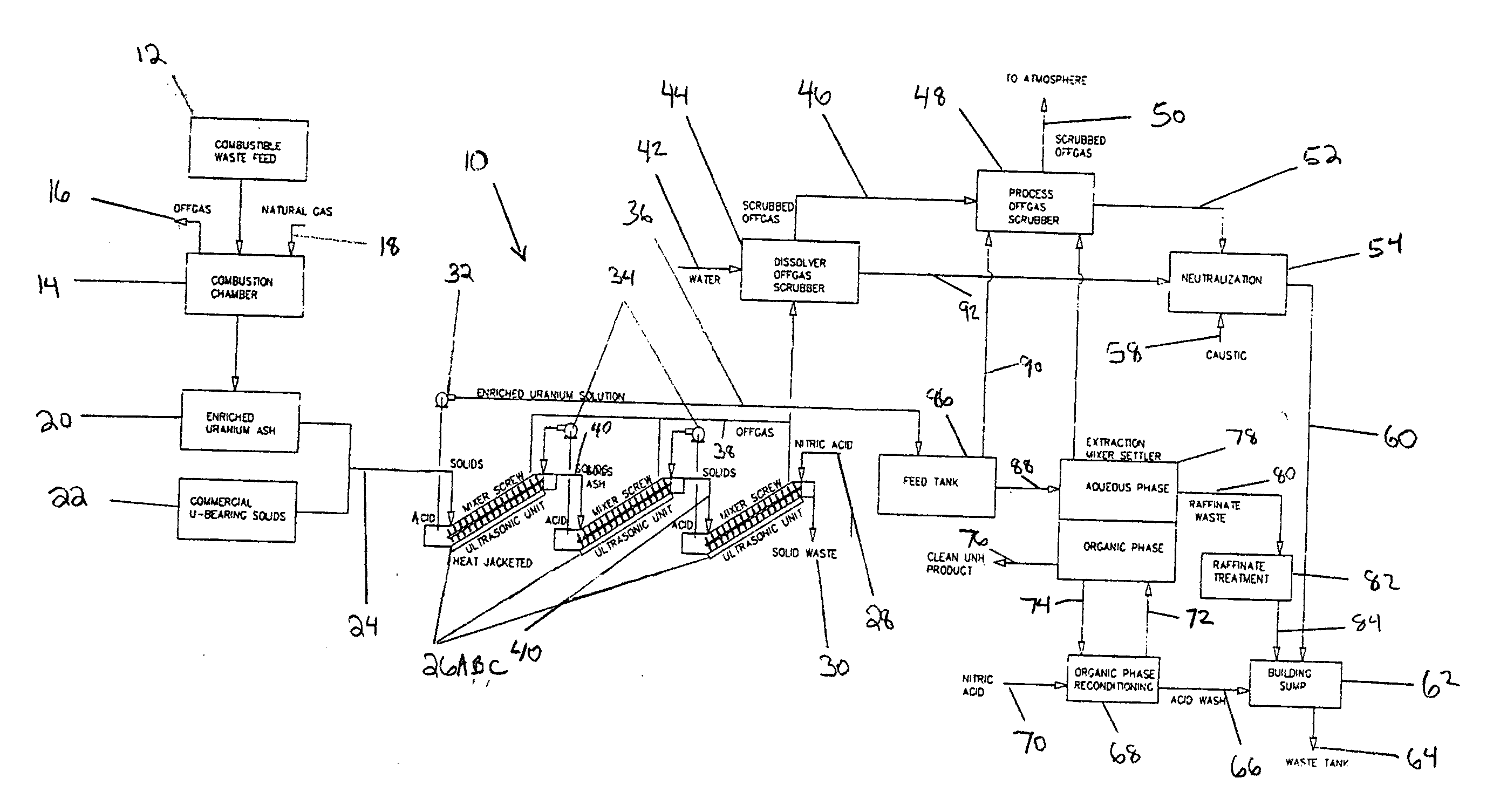
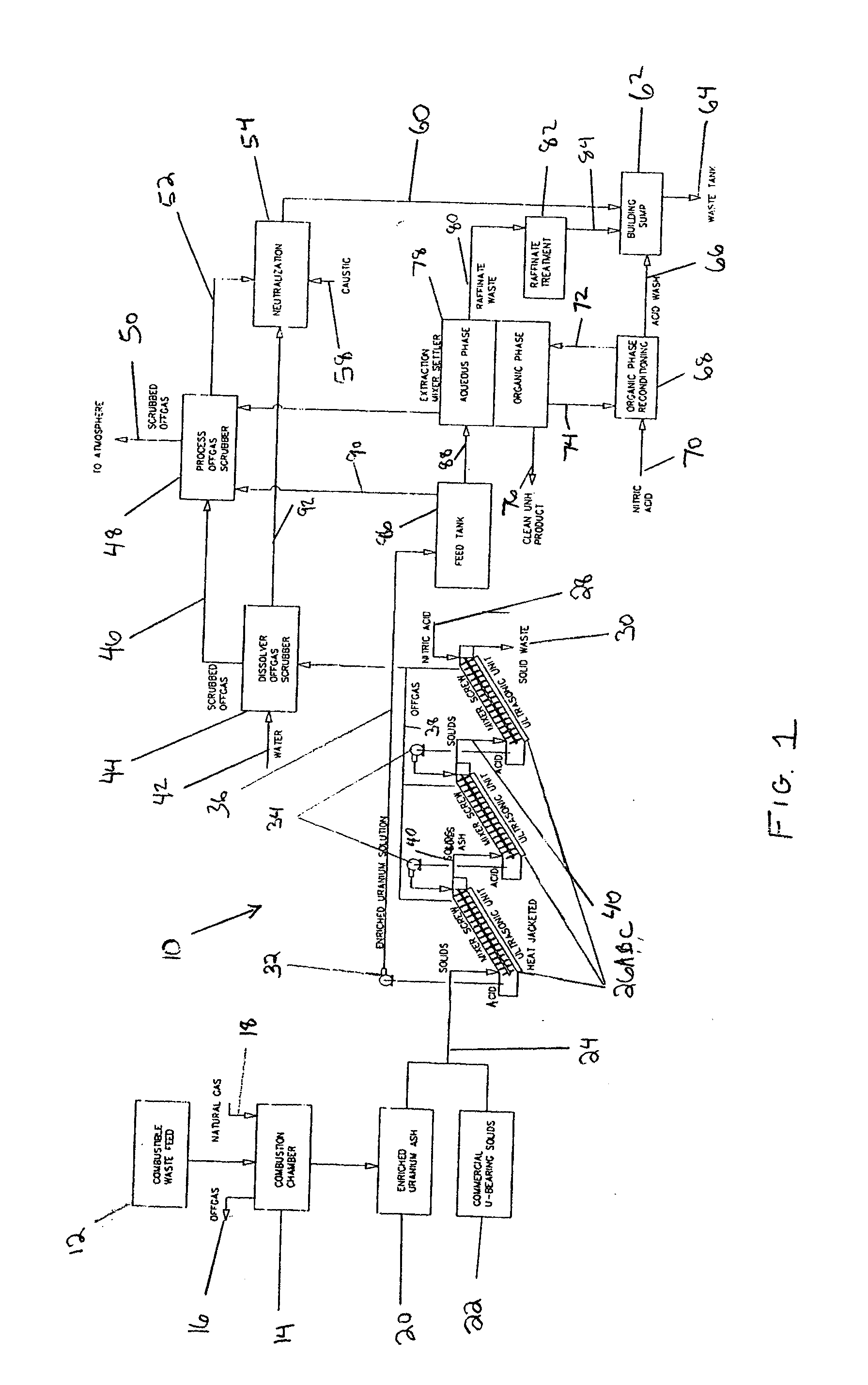
[0015] Referring to FIG. 1, an arrangement 10 using an ultrasonic counter-current screw extractor for uranium recovery is illustrated. The arrangement 10 is used to treat solids, such as incinerator ash and / or soils, that are contaminated with uranium. In the arrangement, a combustible waste feed 12 feeds into a combustion chamber 14 of an incinerator for ultimate disposition. The combustion chamber 14 may be fed with an input of natural gas 18, or other combustible power source such as oil as a non-limiting example. Gaseous components resulting from the combustion process in the combustion chamber 14 are released from the combustion chamber 14 by an offgas outlet 16 which, as illustrated, releases the gaseous components generated in the combustion chamber 14 to the atmosphere. Although not illustrated, further processing steps may occur for the offgas exiting the combustion chamber in order to reduce the ultimate amount of pollutants discharged to the atmosphere. Such treatment ste...


PUM

PropertyMeasurementUnit
Concentrationaaaaaaaaaa
Energyaaaaaaaaaa

Abstract

An apparatus and method to remove uranium from a body of material wherein the method includes the steps of depositing the body of solid material in an ultrasonic extractor and depositing an amount of acid in the ultrasonic extractor. The method also provides for the steps of heating a jacket of the ultrasonic extractor, transporting the body of solid material in the ultrasonic extractor and the amount of acid such that the body of solid material and the acid contact each other inside the heated ultrasonic extractor while the ultrasonic extractor provides ultrasonic energy to both the body of solid material and the amount of acid, wherein the amount of acid strips uranium from the body of solid material. The method further provides for collecting the amount of acid and the body of solid material in the ultrasonic extractor in different positions, transporting the amount of acid with the stripped uranium to an extraction mixer settler, and settling uranium product from the extraction mixer settler.

Description

FIELD OF THE INVENTION [0001] The present invention relates to a method and device for uranium recovery. More specifically, the present invention provides an apparatus and method for recovering uranium from a body of material using an ultrasonic counter-current screw extractor. BACKGROUND INFORMATION [0002] Contaminated materials, such as incinerator ash and soils, pose many challenges for the uranium processing industry. At uranium processing sites, incinerator ash and soils may be contaminated with different materials, including heavy metals, uranium and other radioactive materials. Uranium materials, when present in such solids, may be either uniformly distributed throughout the solids or may be concentrated in discrete sections. Removal of uranium materials from these solids is particularly difficult as, in most instances, a non-uniform distribution of uranium at low concentration levels occurs. Material treatment / separation techniques which use a mechanical separation technique...

Claims


Application Information

Patent Timeline
IPC IPC(8): C01G56/00
CPCB01D11/0226B01D11/0276B01F7/021C01G43/00C22B3/065C22B3/22C22B7/007C22B7/02C22B60/0239C22B60/026G21F9/30B01F7/00391B01D11/0261B01D11/0284Y02P10/20B01F27/114B01F27/61
Inventor KIMURA, RICHARD THADDEUS
Owner AREVA NP INC
Learn More