

Chain guide
a chain guide and chain technology, applied in the direction of belts/chains/gearrings, mechanical instruments, belts/chains/gears, etc., can solve the problems of limited cost, increased size and etc., to increase the size or weight increase the bending rigidity of the entire chain guide, and reduce the effect of cos
- Summary
- Abstract
- Description
- Claims
- Application Information
AI Technical Summary
Benefits of technology
Problems solved by technology
Method used
Image

Examples
first embodiment
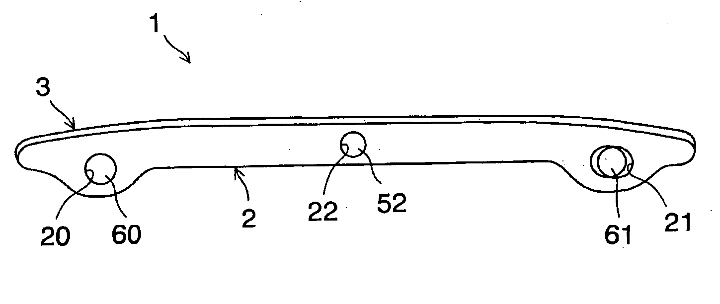
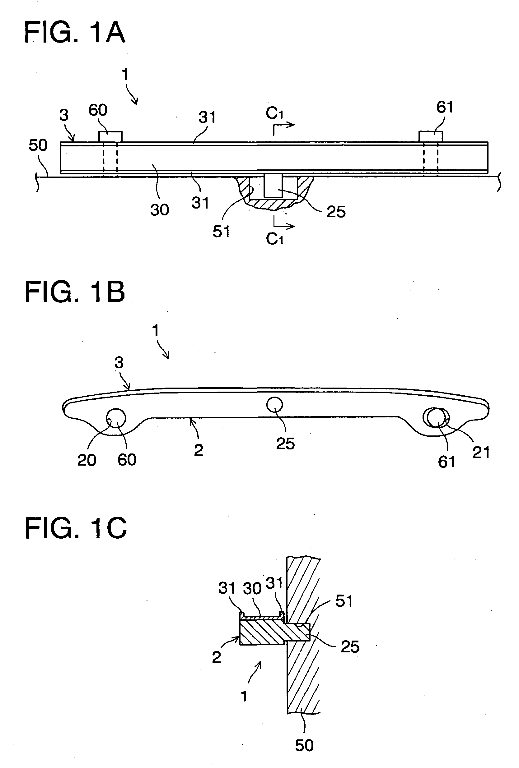
[0029] As shown in FIGS. 1A to 1C, a chain guide 1 includes a guide body 2. The guide body is preferably formed of synthetic resin, aluminum die cast, or the like. The chain guide 1 also includes a shoe 3 preferably formed of synthetic resin or the like, which is fixedly attached on or integrated with the guide body 2.
[0030] A pair of bolt holes 20, 21 are formed at opposite end portions of the guide body 2 to receive installation bolts 60, 61 to install the chain guide 1 on an engine part such as an engine block (or engine front cover) 50. The bolt hole 21 is preferably an elongated aperture extending along the length of the guide body 2, in the left and right direction of FIG. 1B, in order to absorb thermal expansion of the guide body 2 due to elevated temperatures in the engine during operation.
[0031] An engaging protrusion 25 that protrudes sideways from the guide body 2 is provided at the central position in the elongated direction of the guide body 2. The engaging protrusion...
second embodiment
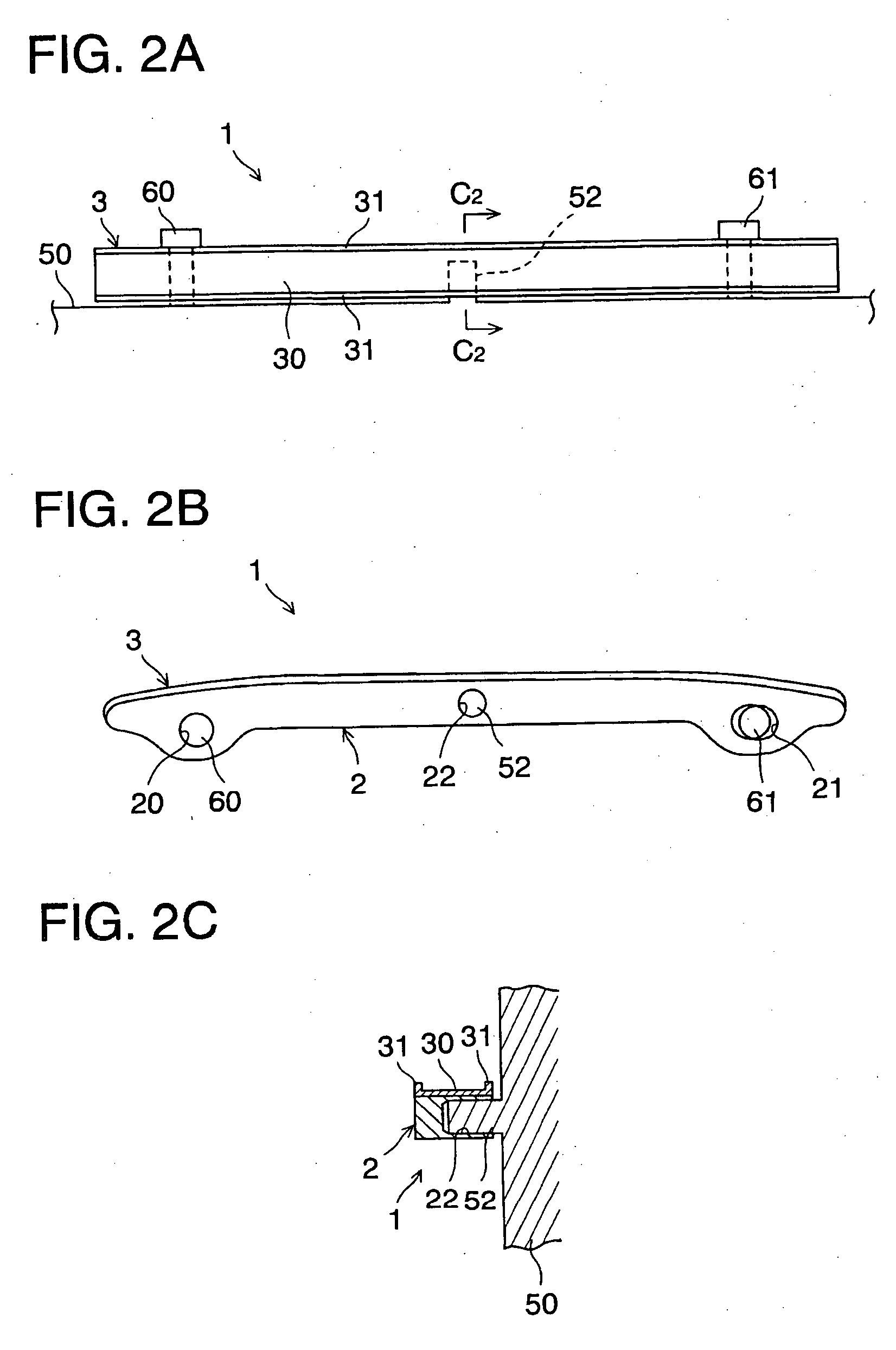
[0036]FIGS. 2A to 2C show a second embodiment of the present invention. In these drawings, like reference numbers indicate identical or functionally similar elements.
[0037] In the second embodiment, in contrast to the first embodiment, an engaging protrusion 52 is preferably provided on the side of the engine block 50 and an engagement hole 22 engageable with the engaging protrusion 52 is preferably formed at a central position of the guide body 2 in the elongated direction. The engaging protrusion 52 is preferably a solid cylindrical protrusion or a prismatic protrusion. In operation, when the chain imparts compressive force, the guide body 2 is supported by the engaging protrusion 52 of the engine block 50 and thus the bending rigidity of the entire chain guide increases similar to the first embodiment of the present invention. Moreover, since the engaging protrusion 52 of the engine block 50 is merely inserted into the engagement hole 22 of the guide body 2, cost increases are l...
third embodiment
[0039]FIGS. 3A to 3C show a third embodiment of the present invention. In these drawings, like reference numbers indicate identical or functionally similar elements.
[0040] In the third embodiment, in contrast to the first and second embodiments, a plate-like protrusion 53 is formed on the side of the engine block 50 and the lower surface of the guide body 2 is supported from below by the plate-like protrusion 53.
[0041] In operation, when the chain imparts compressive force, the guide body 2 is supported by the plate-like protrusion 53 of the engine block 50 and thus the bending rigidity of the entire chain guide increases similar to the first and second embodiments of the present invention. Moreover, since the plate-like protrusion 53 is merely provided on the engine block 50, an increase in costs is restrained without substantially increasing the size and the weight of the entire chain guide and without altering the molds for the chain guide. Also, thermal expansion of the guide ...
PUM
 Abstract
Description
Claims
Application Information