Resistive shunt valve

a shunt valve and resistive technology, applied in the field of hydrocephalus, can solve the problems of csf overdrainage, headache, nausea, and most shunt designs have suffered from overdrainage tendencies, and achieve the effects of minimizing valve occlusion, preventing overdrainage of csf, and minimizing occlusion of valv

Inactive Publication Date: 2006-04-27
PORTNOY HAROLD D
View PDF43 Cites 30 Cited by
  • Summary
  • Abstract
  • Description
  • Claims
  • Application Information

AI Technical Summary

Benefits of technology

[0011] A resistive shunt valve (RSV) for preventing overdrainage of cerebrospinal fluid (CSF) is provided. The RSV comprises a conduit housing and a valve member. The conduit housing is adapted for continuously conveying a flow of CSF with the valve member metering the flow rate of CSF. The conduit housing and the valve member are adapted for minimizing occlusion of the valve by CSF debris. Further, the housing and the valve member are adapted to minimize overdrainage of CSF.

Problems solved by technology

To date, most shunt designs have suffered from overdrainage tendencies.
Overdraining CSF can present headaches, nausea, subdural hematoma, premature closure of cranial sutures, repeated shunt obstruction and other undesirable symptoms in a shunted patient.
The major shortcoming of the anti-siphon type valves is that the diaphragm may become encapsulated by scar tissue and cause the valve to fail either in a fully open or closed position.
One drawback of this shunt valve system is the difficulty in determining a sufficient total ball mass in view of the varying hydrostatic pressure that is caused by the constant movement of the distal catheter in the peritoneal cavity.
In addition, this system can completely block the flow of CSF and thus may not sufficiently drain CSF under certain circumstances.
A further drawback is created when the valve is not implanted along the long axis of the patient.
Again, this device suffers from the disadvantage of readily unseating when the device is positioned at any angle other than absolute vertical.
Because no device can be implanted in an absolute vertical position, and patient posture constantly changes, this valve design likewise lacks the ability to adequately control the leak rate of CSF to maintain desired ICP.

Method used


Image

  • Resistive shunt valve
  • Resistive shunt valve
  • Resistive shunt valve

Examples


Embodiment Construction

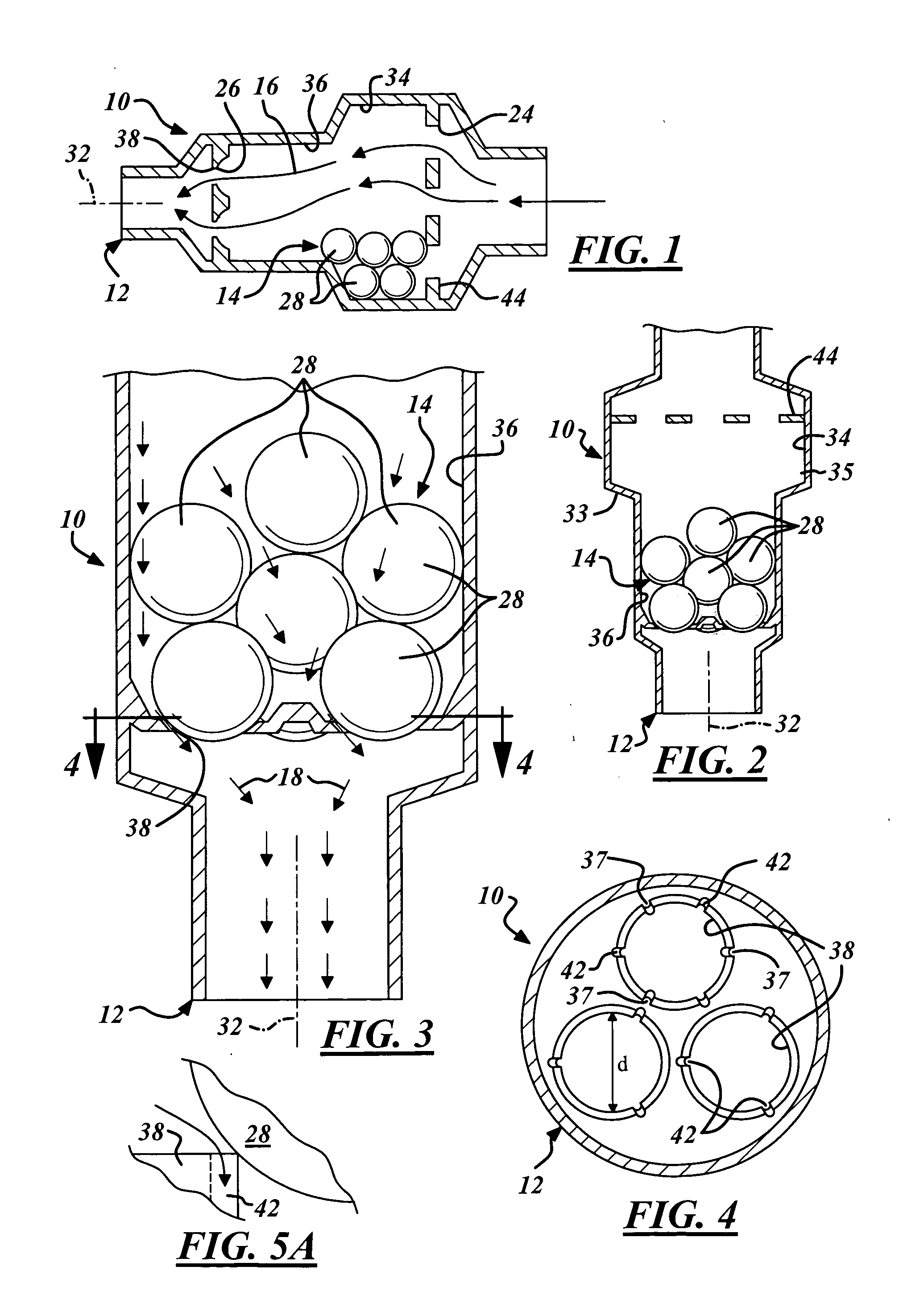
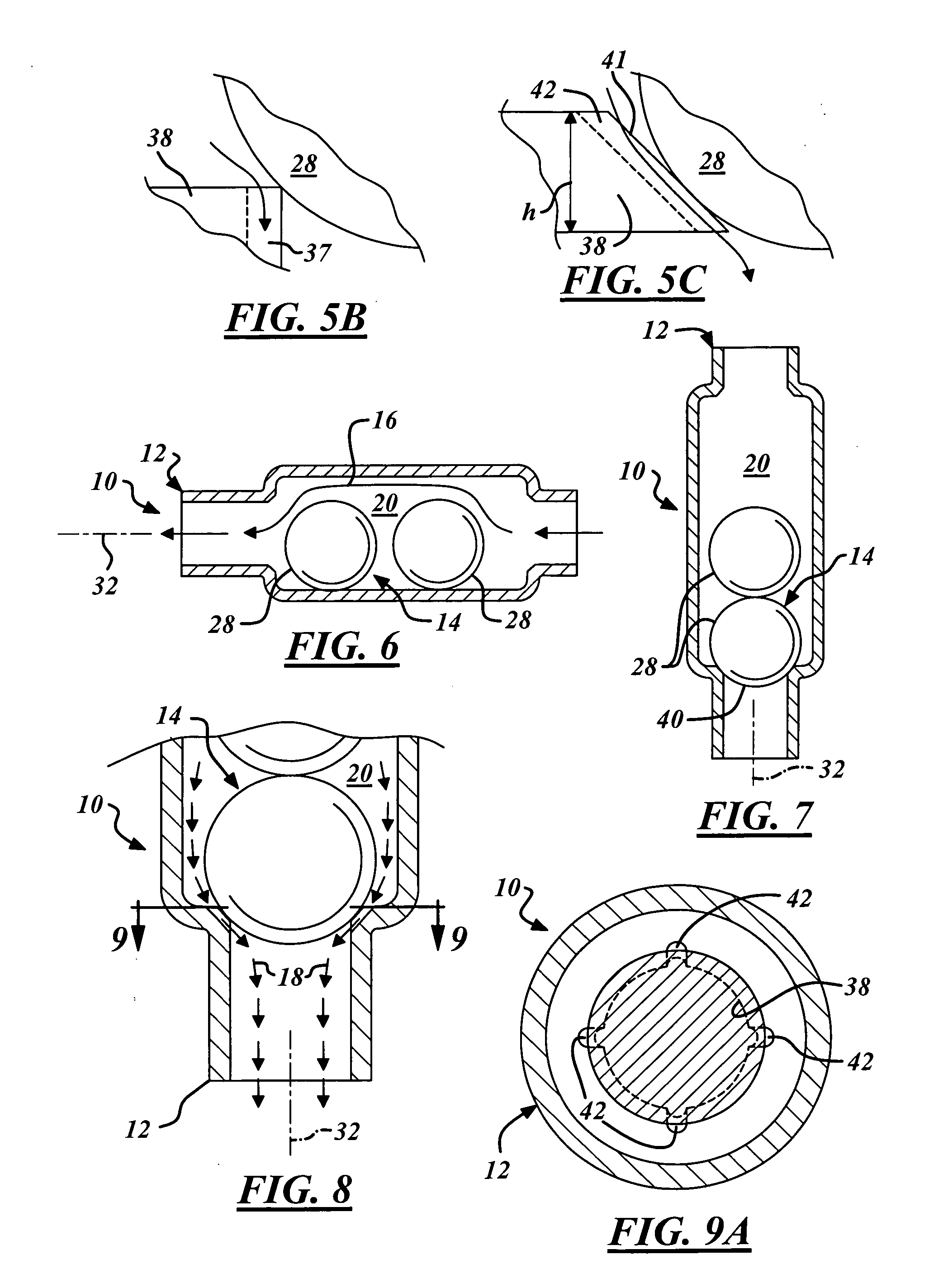
[0034] In the following figures, the same reference numerals are used to identify the same or similar components in the various representative views.

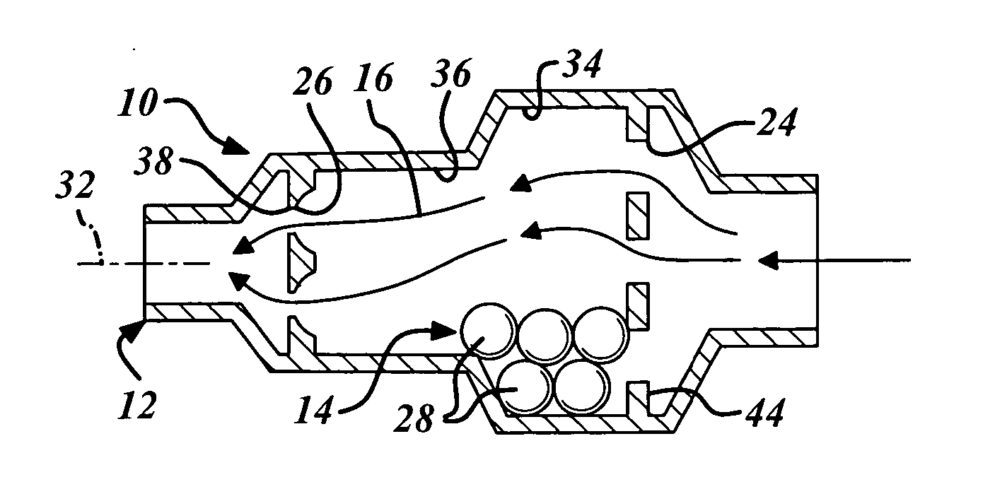
[0035] The present invention is particularly suited for a resistive shunt valve for preventing overdrainage of cerebrospinal fluid (CSF) for a hydrocephalic patient where the valve in the vertical position should not drain CSF at more than the rate of approximately 0.3-0.5 ml / min. In this regard, the embodiments described herein employ features where the context permits, e.g. when a specific result or advantage of the claimed invention is desired. However, it is contemplated that the resistive shunt valve can instead be utilized for hydraulic systems or a variety of other suitable applications. To that end, a variety of other embodiments are contemplated having different combinations of the described features, having features other than those described herein, or even lacking one or more of those features.

[0036] An embodiment of a res...


PUM


Abstract

A resistive shunt valve (RSV) for draining cerebrospinal fluid. The RSV is comprised of a conduit housing and a valve member. The conduit housing is adapted for continuously conveying a flow of cerebrospinal fluid (CSF) with the valve member metering the flow of CSF therethrough. The valve member has a plurality of balls and at least one valve seat, with the number of balls being greater than the number of valve seats. The balls register within the valve seats in the direction of CSF flow. Small notches or irregularities are provided in the valve seats. Metering of CSF can be controlled by the housing diameter, ball diameter, number of balls, ball weight, irregularity of the valve seats, surface characteristics of the ball, and ball material.

Description

CROSS REFERENCE TO RELATED APPLICATION [0001] The present application claims priority from U.S. Provisional Application Ser. No. 60 / 620,945 filed Oct. 21, 2004, and entitled “Resistive Valve For Preventing Overdrainage In A Shunt For Hydrocephalus.”TECHNICAL FIELD [0002] The present invention relates generally to hydrocephalus, and more particularly to a resistive shunt valve having a simple and robust construction to prevent overdrainage of cerebrospinal fluid. BACKGROUND [0003] Shunts play a pivotal role in preventing damage to the nervous systems of hydrocephalic patients. For years, shunts have been designed with the goal of properly draining the cerebrospinal fluid (CSF) accumulating within the cerebral ventricles to regulate intracranial pressure (ICP). [0004] A shunt for hydrocephalus treatment typically includes an intracranial catheter connected to a valve that regulates flow of CSF, and a distal catheter to a cavity within the patient's body. In general, the cavity is the ...

Claims


Application Information

Patent Timeline
Patent Type & Authority Applications(United States)
IPC IPC(8): A61M5/00
CPCA61M27/002A61M27/006
Inventor PORTNOY, HAROLD D.
Owner PORTNOY HAROLD D
Why Eureka
Try Eureka