Angular position sensor-based engine controller system

a technology of angular position and sensor, applied in the direction of electric control, brake system, instruments, etc., can solve the problem of restricting the performance achieved by such controllers

Active Publication Date: 2006-04-27
LITENS AUTOMOTIVE INC
View PDF23 Cites 21 Cited by
  • Summary
  • Abstract
  • Description
  • Claims
  • Application Information

AI Technical Summary

Benefits of technology

[0005] According to a first aspect of the present invention, there is provided an engine controller system for an engine comprising: at least one processor; and at least one angular position sensor for association with a rotating engine component, said sensor providing signals to said processor indicating the angular position of the component, wherein the processor processes said signals and produces at least one output control signal to alter operation of said engine.

Problems solved by technology

While significant performance and operating economy improvements have been obtained from such engine controllers, problems do exist when attempts are made to further improve the performance and operating economies achieved with these systems.
In particular, present engine controllers do not obtain or process, with sufficient accuracy, the angular position of various engine components, such as camshafts and / or crankshafts and this failure limits the performance achieved by such controllers.

Method used


Image

  • Angular position sensor-based engine controller system
  • Angular position sensor-based engine controller system
  • Angular position sensor-based engine controller system

Examples


Embodiment Construction

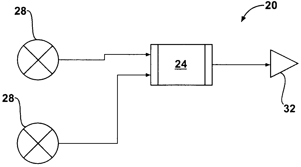
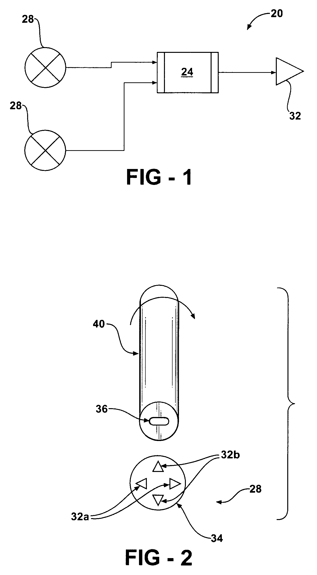
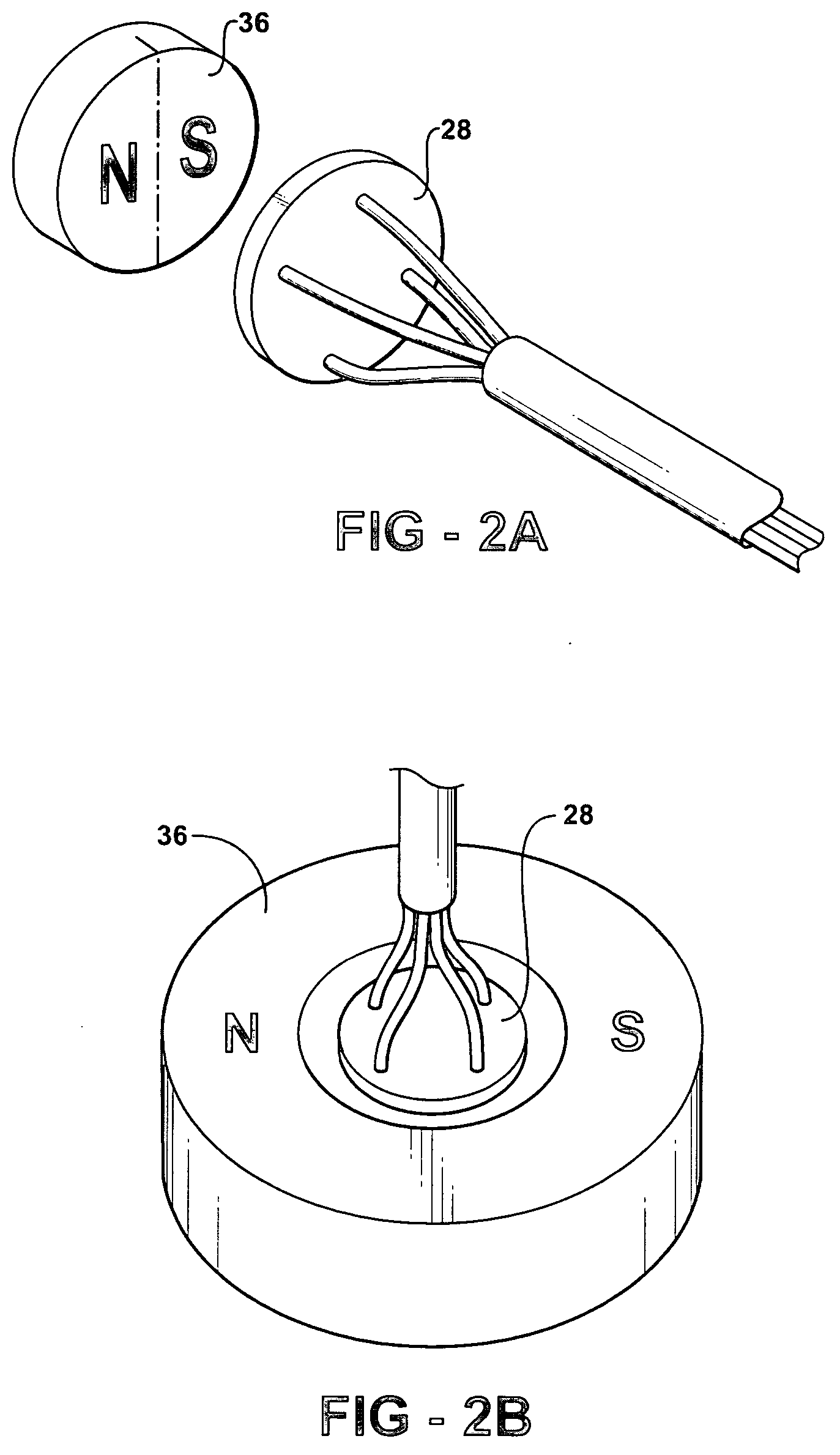
[0028] An engine controller system in accordance with the present invention is indicated generally at 20 in FIG. 1. Engine controller system 20 includes at least one processor unit 24, at least one absolute angular position sensor 28 and an actuator 32 which is operated responsive to a control signal from processor unit 24.

[0029] As will be apparent to those of skill in the art, engine controller system 20 is not limited to only having one processor 24 and, in fact, system 20 can include multiple processors 24, including one or more processors 24 which can be dedicated to processing signals received from angular position sensors 28 and one or more processors 24 which can be dedicated to executing an engine component control algorithm, as discussed further below. In such a case, each processor 24 need not be the same as each other processor 24. For example, a processor 24 receiving signals from angular position sensor 28 can be a microcontroller with A / D converters, etc. while a pro...


PUM


Abstract

An engine controller system employs angular position sensors which are operable to very accurately determine the position of rotating engine members. Information about the angular position of the engine members is used to alter operation of the engine for improved efficiency and/or reduced emissions from the engine. The angular position of the crankshaft and camshafts can be determined by affixing a dipole magnet to each of them such that the magnet field of the magnet rotates with the rotating member and then placing a angular position sensor adjacent each rotating member to detect the rotation of each magnetic field. In another embodiment, the angular position of each end of at least one of the rotating members is determined to allow the processor to determine the torsional deflection of the member and the engine controller system is responsive to that determined deflection to further alter operation of the engine.

Description

FIELD OF THE INVENTION [0001] The present invention relates to an engine controller system for an internal combustion engine. More specifically, the present invention relates to an engine controller system which obtains and processes angular position information relating to the operation of an internal combustion engine to control the operation of that engine. BACKGROUND OF THE INVENTION [0002] Engine controllers employing microprocessors are well known and have been commonly employed to control fuel injection and other engine systems in gasoline and diesel internal combustion engines. Generally, such controllers receive a variety of signals from sensors to determine, for example, the speed and / or position of the crankshaft, the mass flow rate of air entering the inlet manifold, the engine operating temperature, etc. The received signals are processed by the engine controller which then produces signals controlling the operation of the fuel injectors and / or other aspects of the oper...

Claims


Application Information

Patent Timeline
Patent Type & Authority Applications(United States)
IPC IPC(8): F02D41/30F02P7/067
CPCF02D41/009F02D2041/001F02P7/07F02P9/005G01D5/145
Inventor SPICER, GARY J.STANIEWICZ, ZBYSLAWCLELAND, TERRY P.
Owner LITENS AUTOMOTIVE INC
Why Eureka
Try Eureka