

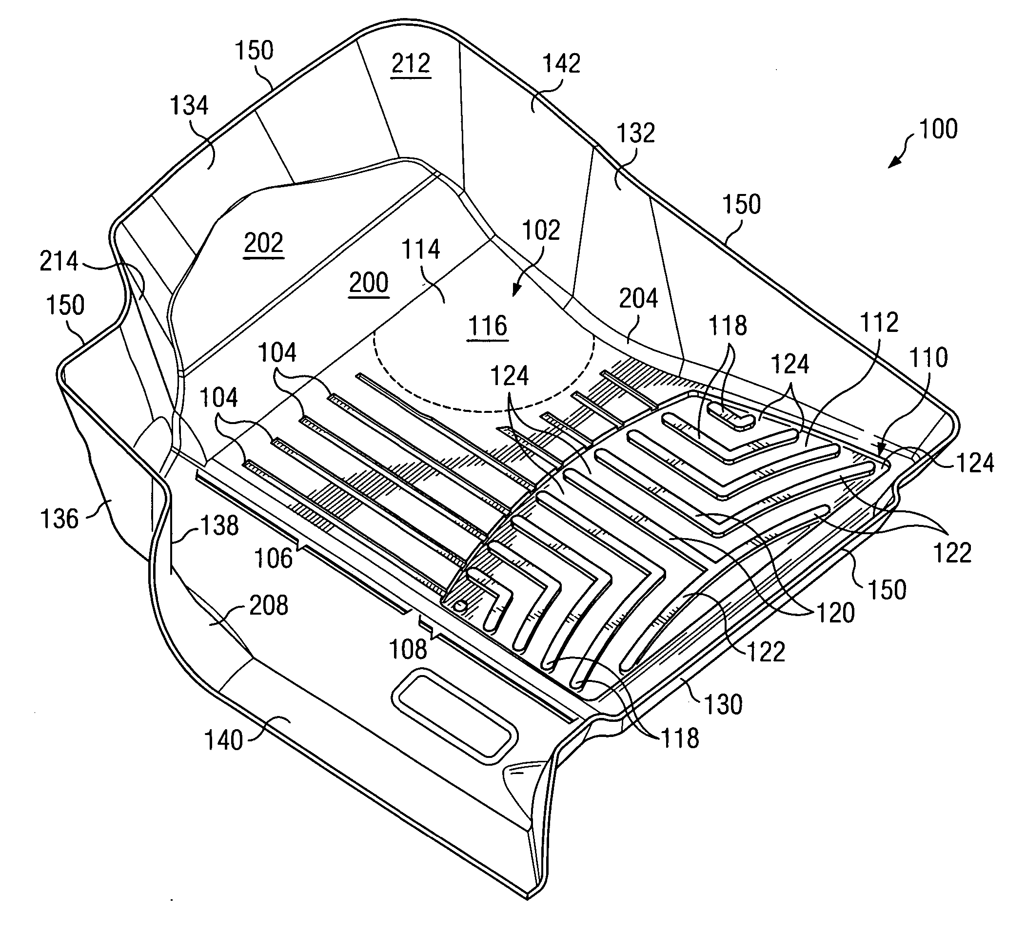
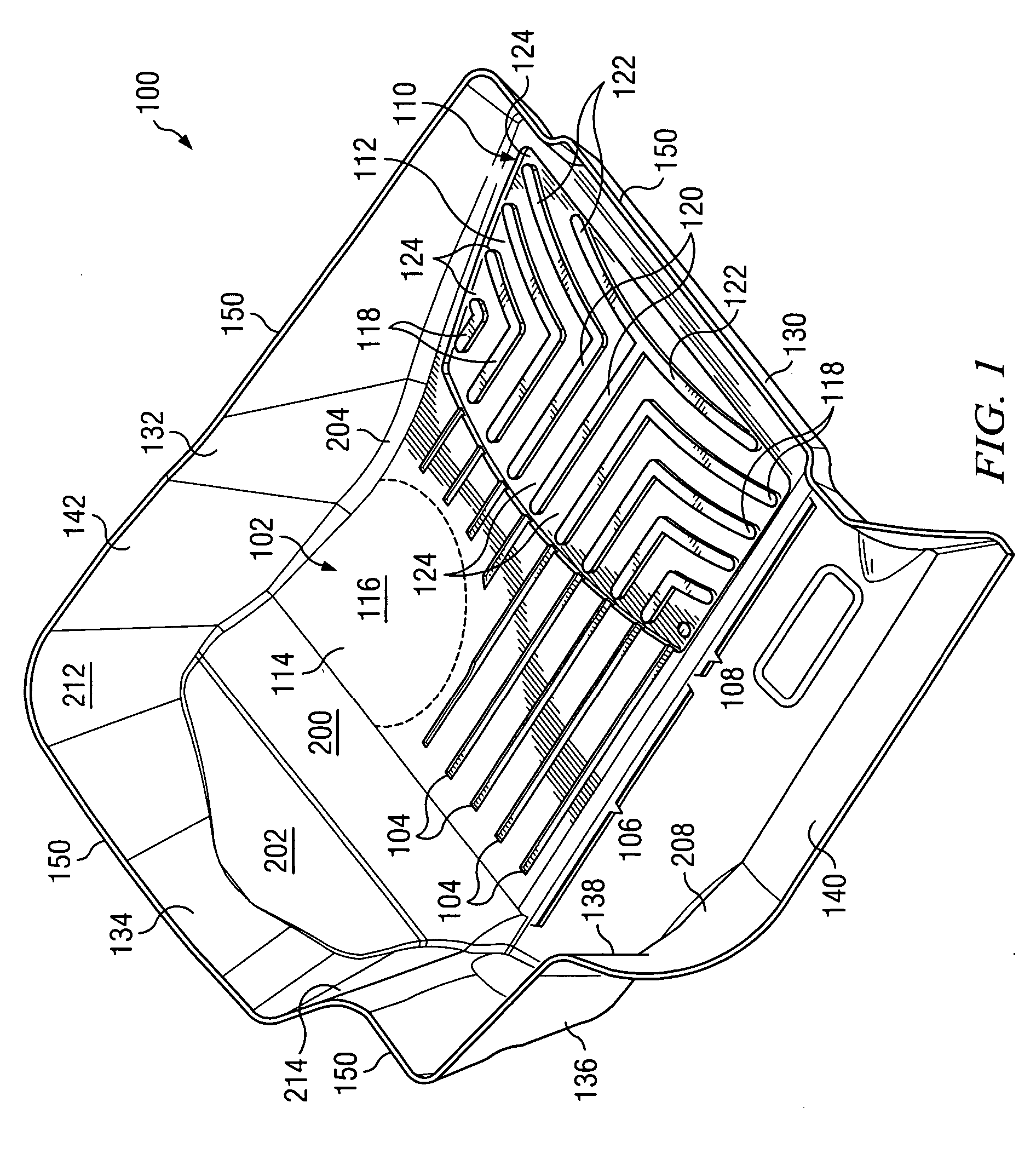
Close-conforming vehicle floor tray with reservoir
- Summary
- Abstract
- Description
- Claims
- Application Information
AI Technical Summary
Benefits of technology
Problems solved by technology
Method used
Image


Examples
example 1
[0095] These tests determined static and kinetic coefficients of friction of a sheet of triextrusion material with respect to an object meant to emulate an typical occupant shoe outsole. This “shoe” was composed of Shore A Durometer 60 neoprene rubber, formed as a “sled” measuring 2.5 in. (6.35 cm)×2.5 in. (6.35 cm)×0.238 in. (0.605 cm). The “shoes” were drawn across an upper, textured surface of a 0.120 in. (0.305 cm) triextrusion sheet formed according to a preferred embodiment of the invention and measuring 4 in. (10.2 cm)×12 in. (30.5 cm), the test performed according to the procedure set forth in ASTM D 1894-01. The triextrusion sheet had, as its top layer, a blend of 75 wt. pct. VYRAM® Grade 101-75 / 25 wt. pct. HMPE. The core layer was 75 wt. pct. HMPE / 25 wt. pct. VYRAM® Grade 101-75. The bottom layer was a blend of 25 wt. pct. HMPE / 75 wt. pct. VYRAM® Grade 101-75. The bottom and top layers each comprised about 12.5% of the sheet thickness while the middle core layer comprised ...
example 2
[0096] Five neoprene rubber “sleds” fabricated as above were drawn across a 4 in. (10.1 cm)×12 in. (30.5 cm) sheet of a single-extrusion 75 wt. pct. HMPE / 25 wt. pct. VYRAM® Grade 101-75, according to ASTM D 1894-01. Results are tabulated below.
SledStaticKineticSledKineticWeightCoefficientLoadWeightCoefficientTest NumberStatic Load (g)(g)of Friction(g)(g)of Friction1157200.10.785162200.10.8102151200.00.755148200.00.7403163200.10.815170200.00.8504146200.10.730148200.10.7405154200.10.770155200.10.775Average0.7710.783Std. Dev.0.0320.047
[0097] The above tests show that with respect to a typical shoe sole composition, a material consisting mostly of a thermoplastic elastomer like VYRAM® exhibits a higher coefficient of friction than a material consisting mostly of a high molecular weight polyolefin.
example 3
[0098] These tests compared the tensile strength of a sheet of triextruded material as above described with a sheet of single-extruded blend of material consisting of 75 wt. pct. VYRAM®, Grade 101-75, and 25 wt. pct. HMPE, and further with a sheet of a single-extruded blend of material of 75 wt. pct. HMPE and 25 wt. pct. VYRAM® Grade 101-75. The tested single-extruded VYRAM®-dominated sheet was approximately 0.070 in. (0.178 cm) thick, while the HMPE-dominated sheet was approximately 0.137 in. (0.348 cm) thick. The triextrusion sheet was about 0.120 in. (0.305 cm) thick. The triextrusion sheet, the single-extruded VYRAM®-dominated sheet and the single-extruded HMPE-dominated sheet were die-cut into samples having an average width of 0.250″0.635 cm). The test performed was according to the ASTM D 638-03 testing standard. A cross-head speed of 20 in. (50.8 cm) / min. was used. The extensiometer was set at 1000% based on 1.0″(2.54 cm) gauge length.
[0099] Samples were conditioned at 40 h...
PUM
| Property | Measurement | Unit |
|---|---|---|
| Length | aaaaa | aaaaa |
| Length | aaaaa | aaaaa |
| Length | aaaaa | aaaaa |
Abstract
Description
Claims
Application Information