
Fluorescent X-ray analysis apparatus

a fluorescent x-ray and analysis apparatus technology, applied in the direction of material analysis using wave/particle radiation, instruments, conversion screens, etc., can solve the problems of change in sensitivity due, change in background magnitude, change in detection lower limit, etc., to keep the detection lower limit constant, change the measurement time, the effect of changing the measurement tim

Active Publication Date: 2006-05-04
HITACHI HIGH TECH SCI CORP
View PDF10 Cites 0 Cited by
  • Summary
  • Abstract
  • Description
  • Claims
  • Application Information

AI Technical Summary

Benefits of technology

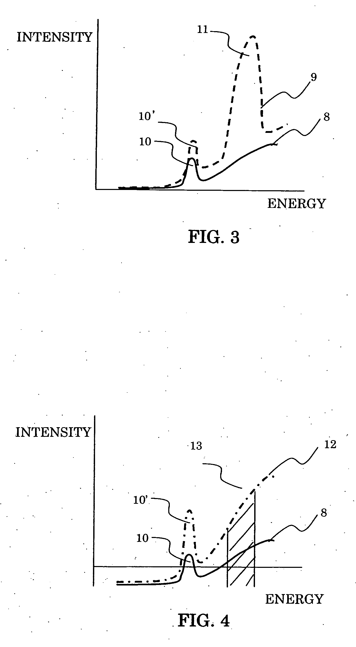
[0014] By having a background intensity automatic-measurement function in the fluorescent X-ray energy position of the heavy metal noted, it becomes possible to keep the detection lower limit constant by recognizing the change in the background intensity due to the influences of the adjoining coexisting elements and the like, and reflecting its information to the above expression of the detection lower limit, thereby changing the measurement time.
[0015] Additionally, by having a function of automatically measuring the sample size even though roughly, it becomes possible to keep the detection lower limit constant by recognizing a change amount of the sensitivity coefficient due to the change in the sample size, and reflecting its information to the above expression of the detection lower limit, thereby changing the measurement time.
[0016] Further, generally in the fluorescent X-ray analysis apparatus, since there is a limit in an X-ray intensity that a detection system can obtain, in order to efficiently measure, it is necessary to change the above intensity of the primary X-ray entering into the sample. However, by this the sensitivity coefficient changes as well. Therefore, it becomes possible to keep the detection lower limit constant by reflecting an information, in which this primary X-ray intensity has been changed, to the above expression of the detection lower limit, thereby changing the measurement time.

Problems solved by technology

As to the fluorescent X-ray analysis apparatus, when analyzing the existence and the concentration of the trace amount heavy metal, such as Cd and Pd, in the resin constituted by C, 0, H and the like, there has been an issue that a detection lower limit changes depending on the sample by a change in sample size, a change in sensitivity due to a difference in main component of the sample, and a change in magnitude of a background due to an influence of a coexisting element in the sample.

Method used


Image

  • Fluorescent X-ray analysis apparatus
  • Fluorescent X-ray analysis apparatus
  • Fluorescent X-ray analysis apparatus

Examples


Embodiment Construction

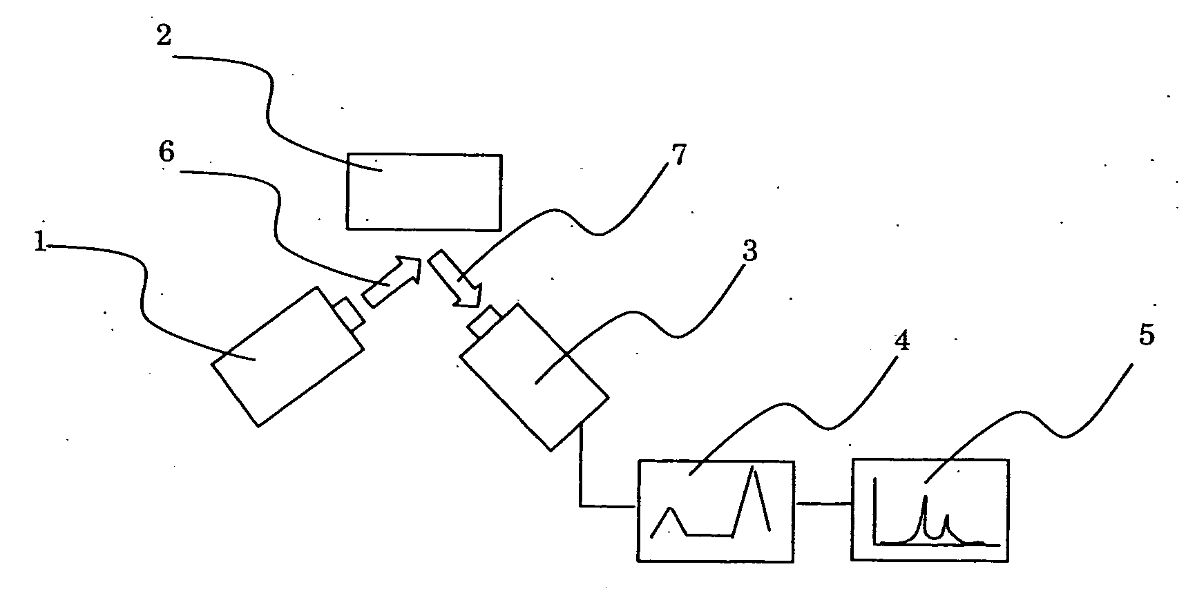
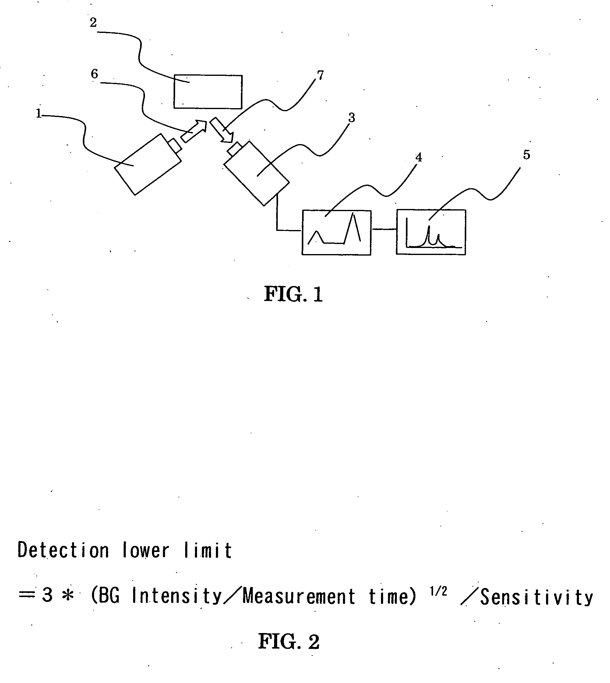
[0021] It is explained about an embodiment of the present invention by referring to the drawings. FIG. 1 is a schematic diagram of a general fluorescent X-ray analysis apparatus. In FIG. 1, a primary X-ray 6 from an X-ray generation unit 1 is irradiated to a sample 2, and a fluorescent X-ray 7 deriving from an element in the sample is induced in the sample 2 and entered into an X-ray detector 3. In the detector 3, an electric signal by the X-ray occurs and, by the fact that this signal is converted in a waveform adjuster 4 into a waveform whose wave height is proportional to an energy, it becomes possible to measure an energy of the X-ray and its number (intensity). Information of that energy and intensity is displayed as a spectrum 5.

[0022]FIG. 2 is one explaining a calculation method of the detection lower limit in the present invention. In the present invention, a relation among the detection lower limit, the background intensity, the measurement time and the sensitivity is made...


PUM


Abstract

The change in the sample size and a change in background intensity due to the coexisting element are measured in real time to thereby automatically change a measurement time, the detection lower limit is kept constant, so that a fluorescent X-ray apparatus is provided that is capable of measuring every time in the same detection lower limit even in a case where there have existed a change in size of a sample, a change in sensitivity due to a difference in main ingredient, and a change of a magnitude in background due to an influence of a coexisting element.

Description

[0001] This application claims priority under 35 U.S.C. §119 to Japanese Patent Application No. 2004-318763 filed Nov. 2, 2004, the entire content of which is hereby incorporated by reference. BACKGROUND OF THE INVENTION [0002] The present invention relates to a fluorescent X-ray analysis apparatus which performs an element analysis / composition analysis of a sample by inducing a fluorescent X-ray by irradiating an X-ray to the sample, and measuring an energy of the fluorescent X-ray and an X-ray intensity. [0003] In a conventional fluorescent X-ray analysis apparatus, when analyzing an existence and a concentration of a trace amount heavy metal, such as Cd and Pd, in a resin constituted by C, 0, H and the like, a measurement has been performed with a measurement time being fixed (for example, Patent Document 1). [Patent Document 1] JP-A-2004-150990 [0004] As to the fluorescent X-ray analysis apparatus, when analyzing the existence and the concentration of the trace amount heavy meta...

Claims


Application Information

Patent Timeline
IPC IPC(8): G01N23/223G01T1/36
CPCG01N2223/076G01N23/223
Inventor MATOBA, YOSHIKI
Owner HITACHI HIGH TECH SCI CORP
Learn More