[0013] The apparatus may be powered using a
hydraulic motor or motors that may be releasably connected to a source of
fluid power on the motive vehicle using suitable fluid conduits. The releasable connection between the articulated arm and the frame and between the source of
fluid power and the
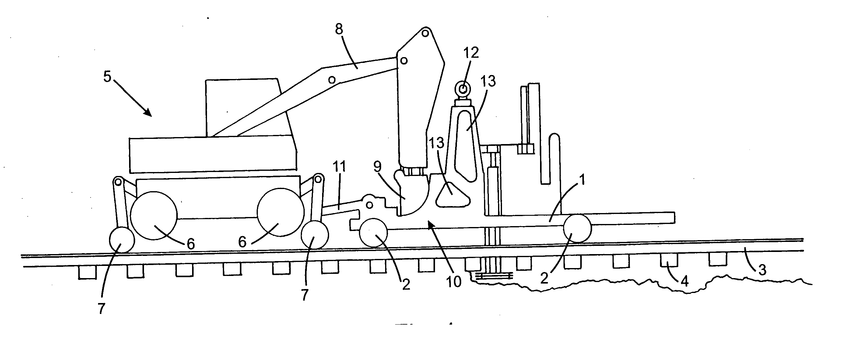
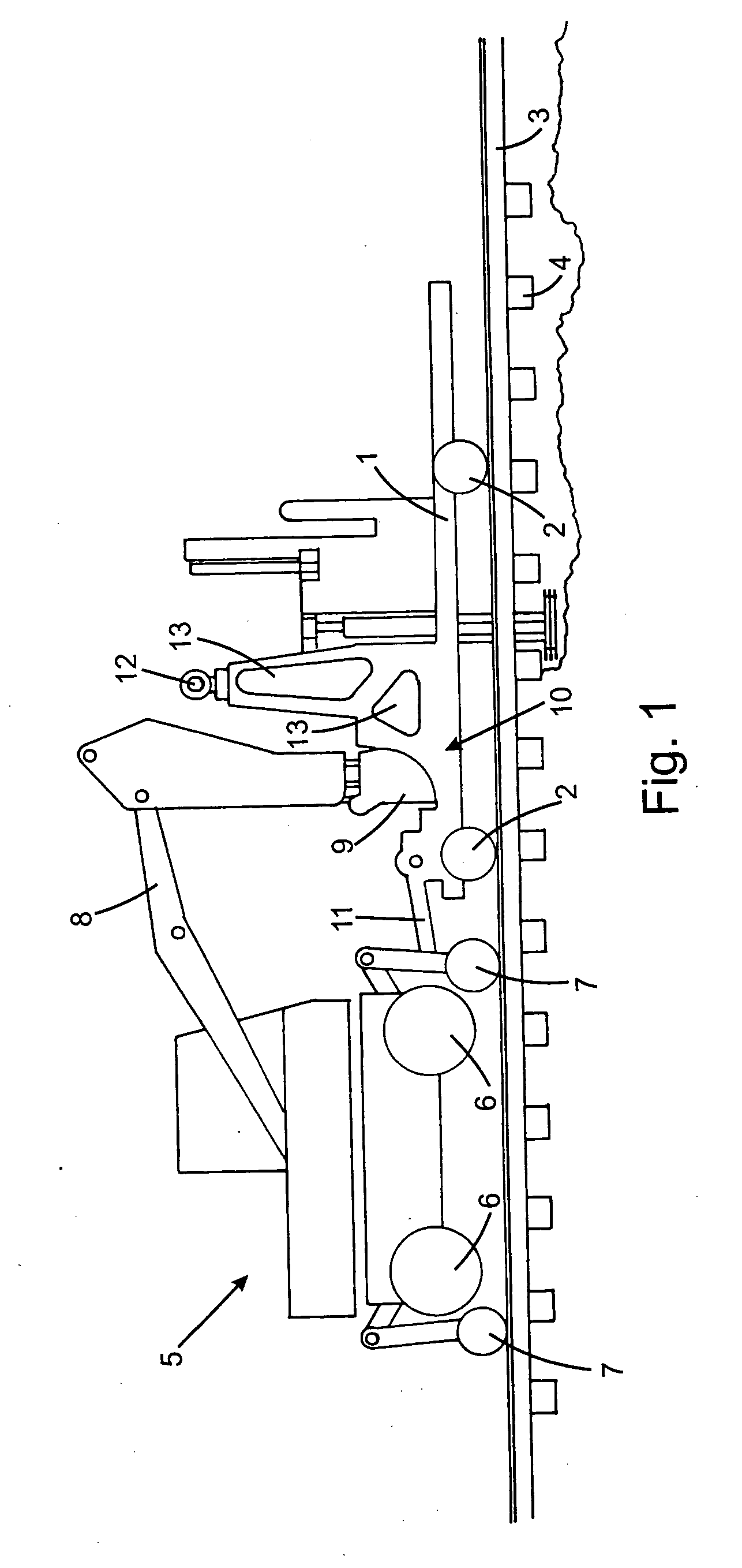
hydraulic motor(s) permits the motive vehicle to be readily de-coupled from the apparatus. In the event of an oncoming train, it is often desirable to remove the apparatus from the tracks to prevent potential damage to either the train, the apparatus, or the motive vehicle. In the prior art, it has been necessary to move the apparatus along the track until a siding has been reached that permits the apparatus and motive vehicle to be moved off-line. In the present invention, the releasable connections permit the apparatus to be readily lifted from the track using the articulated arm of the motive vehicle and set alongside the tracks. The railway wheels may then be raised, permitting the rubber-wheeled
excavator to be moved off of the tracks alongside the apparatus. When the train has passed, the apparatus may be again positioned on the tracks using the excavator and work may be resumed. This saves a tremendous amount of wasted time as compared with prior art ballast excavating machines.
[0015] During ballast excavation, debris may have a tendency to accumulate within the guide frame behind the excavating chain. The apparatus may desirably be equipped with debris clearing holes in the guide frame to permit the debris to naturally fall out of the guide frame and to permit debris to be readily cleared from the guide frame using a high-pressure
water spray or jet of
compressed air. The accumulation of debris can significantly affect the overall weight and balance of the apparatus and the removal of debris is desirable in facilitating the removal of the apparatus from the railway tracks.
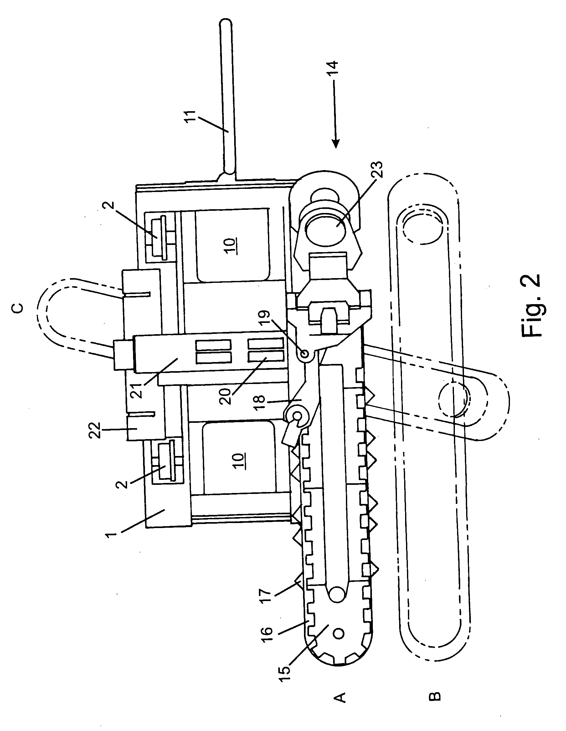
[0017] In the prior art, excavated material quickly accumulates in the vicinity of the outward end of the guide frame, which interferes with the rate of excavation, increases the likelihood for damage to the apparatus, and limits the amount of material that can be removed in each transit of the apparatus along the tracks. To overcome these disadvantages, the present invention is equipped with a first portion and a second portion that is parallel to the first portion but inclined thereto. This second portion serves to elevate the excavated material and deposits the excavated material in a
pile alongside the railway track. The
angle of inclination in some part depends upon the amount of material desired to be removed in a single transit of the apparatus along the tracks. If the
full width of the tracks is to be excavated in a single transit (which normally results in a first portion length in excess of 13 feet), then a greater angle may be required as compared with an excavating unit having a shorter first portion. However, larger inclination angles have the
disadvantage of losing more of the excavated material while elevating, causing the pile to be spread out alongside the tracks and generally reducing the
efficacy of the second portion. It has surprisingly been found that only a small angle is required for proper pile formation, even during full-width
cutting operations. The second portion may be inclined with respect to the first portion at an angle of from 10 to 45 degrees, preferably from 15 to 30 degrees, more preferably from 20 to 23 degrees, yet more preferably about 22 degrees.
[0018] A further benefit of using the smallest allowable inclination angle is found in the excavating chain. Since the excavating chain is required to deflect upwardly as it travels from the first portion to the second portion, the excavating chain may be provided with one or more universal joints between each link. The universal joints may comprise a semi-spherical eye within a complementary bearing race that permits the normally vertical pivot axis between each link to deflect to an
angular orientation as the joint passes from the first portion to the second portion. As the inclination angle of the second portion increases, so too does the required deflection of the
universal joint. In order to keep the chain as robust as possible, it is therefore desirable to utilize the smallest allowable inclination angle in order to reduce the required deflection of the
universal joint. The use of a joining link having two universal joints between each excavating link is desirable in that it allows the
deflection angle of each individual
universal joint to be further reduced.
[0019] Each excavating link of the excavating chain may comprise an outwardly projecting excavating lug having a row of horizontally and vertically spaced apart excavating teeth. The individual teeth may be angled with respect to one another. The row of teeth may form an inclined row angle relative to the direction of movement of the excavating chain. The row angle may correspond to the inclination angle of the second portion so that when the excavating link is on the second portion, the row is substantially horizontal. This facilitates elevation of excavated material using the second portion, thereby reducing the tendency toward pile spreading and further reducing the allowable inclination angle. The row angle may be from 10 to 45 degrees, preferably from 15 to 30 degrees, more preferably from 20 to 23 degrees, yet more preferably about 22 degrees.
[0020] In the present invention, it is desirable that the second portion is substantially aligned with the first portion. This causes the second portion to eject material transversely of the railway track during operation of the excavating unit. If the second portion were not parallel with the first portion, the excavated material would have a tendency to be ejected from the first portion and not elevated using the second portion. Prior art devices have utilized a curved guide shield to prevent this ejection of material; however, a guide shield simply causes the excavated material to accumulate at the curve, reducing the
throughput of the excavating apparatus and increasing the likelihood for excavated material to become lodged, resulting in
mechanical failure. By keeping the second portion substantially parallel with the first portion, the need for any guide shield is reduced and desirably eliminated.

