Method for microscopy, and microscope

a microscopy and microscope technology, applied in the field of microscopy, can solve the problems of unsatisfactory specimen damage and large demands on the light sour

Inactive Publication Date: 2006-05-11
LEICA MICROSYSTEMS CMS GMBH
View PDF3 Cites 8 Cited by
  • Summary
  • Abstract
  • Description
  • Claims
  • Application Information

AI Technical Summary

Benefits of technology

[0012] It is therefore an object of the invention to provide a method for microscopy that reliably and efficiently allows exploitation of nonlinear processes with reduced specimen damage.
[0019] A further object of the invention is to provide a microscope which reliably and efficiently allows an investigation of a specimen exploiting nonlinear processes with reduced specimen impact.
[0021] The invention has the advantage that the method according to the present invention exploits location-dependent optical nonlinearities but makes do with much lower light intensities, the use of the lowest possible light intensities having particular significance especially for biological specimens. Investigation of the specimen to a great depth is also possible.
[0023] In a preferred embodiment, the influencing is a removal of the light components of the illuminating light that comprise wavelengths within the detection spectral region. In another embodiment, the influencing contains a modification of the polarization state of the light components of the illuminating light that comprise wavelengths within the detection spectral region. The modification of the polarization state can encompass, in particular, a rotation of a linear polarization. Rotation of the linear polarization direction makes the detection light in the detection spectral region distinguishable from the illuminating light.

Problems solved by technology

It must be noted, however, that illuminating light having at least two different illuminating light wavelengths, at high light power levels, is required for this method.
The aforesaid methods are disadvantageous in that high light power levels are necessary, resulting on the one hand in great demands on the light source and on the other hand in undesirable damage to the specimen, for example due to bleaching.

Method used


Image

  • Method for microscopy, and microscope
  • Method for microscopy, and microscope
  • Method for microscopy, and microscope

Examples


Embodiment Construction

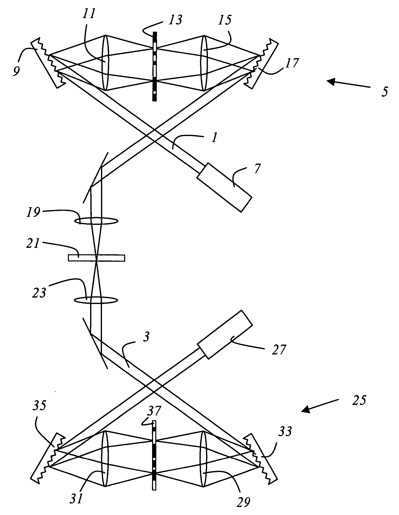
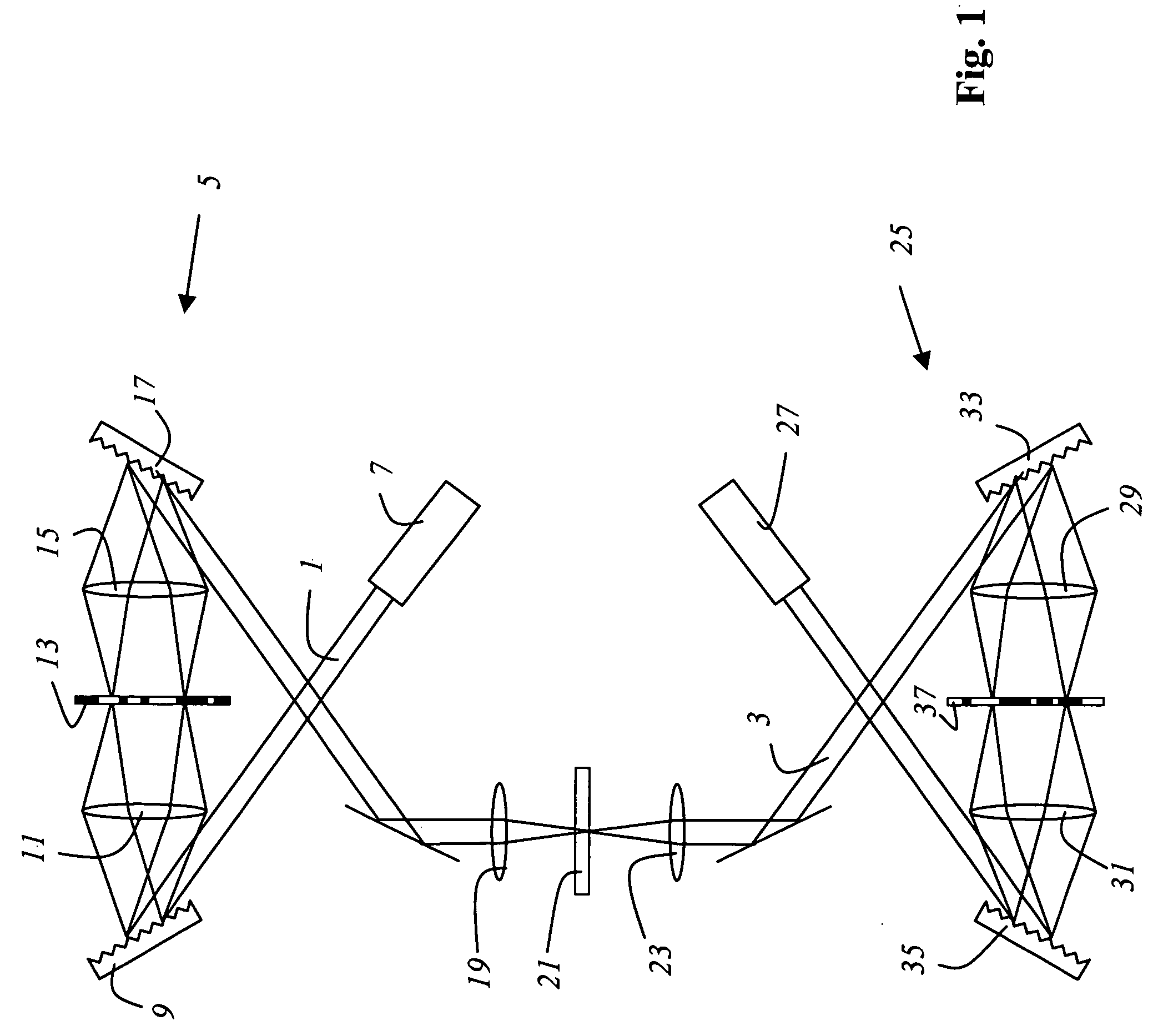
[0036]FIG. 1 schematically shows a microscope according to the present invention that is embodied as a scanning microscope. The optical components for guiding, directing, and focusing illuminating light beam 1 (generated by a pulsed laser 7) and detection light beam 3, and the apparatuses for evaluating the detection light data and displaying an image of the specimen, are not shown in the interest of better clarity. These components are sufficiently familiar to one skilled in the art.

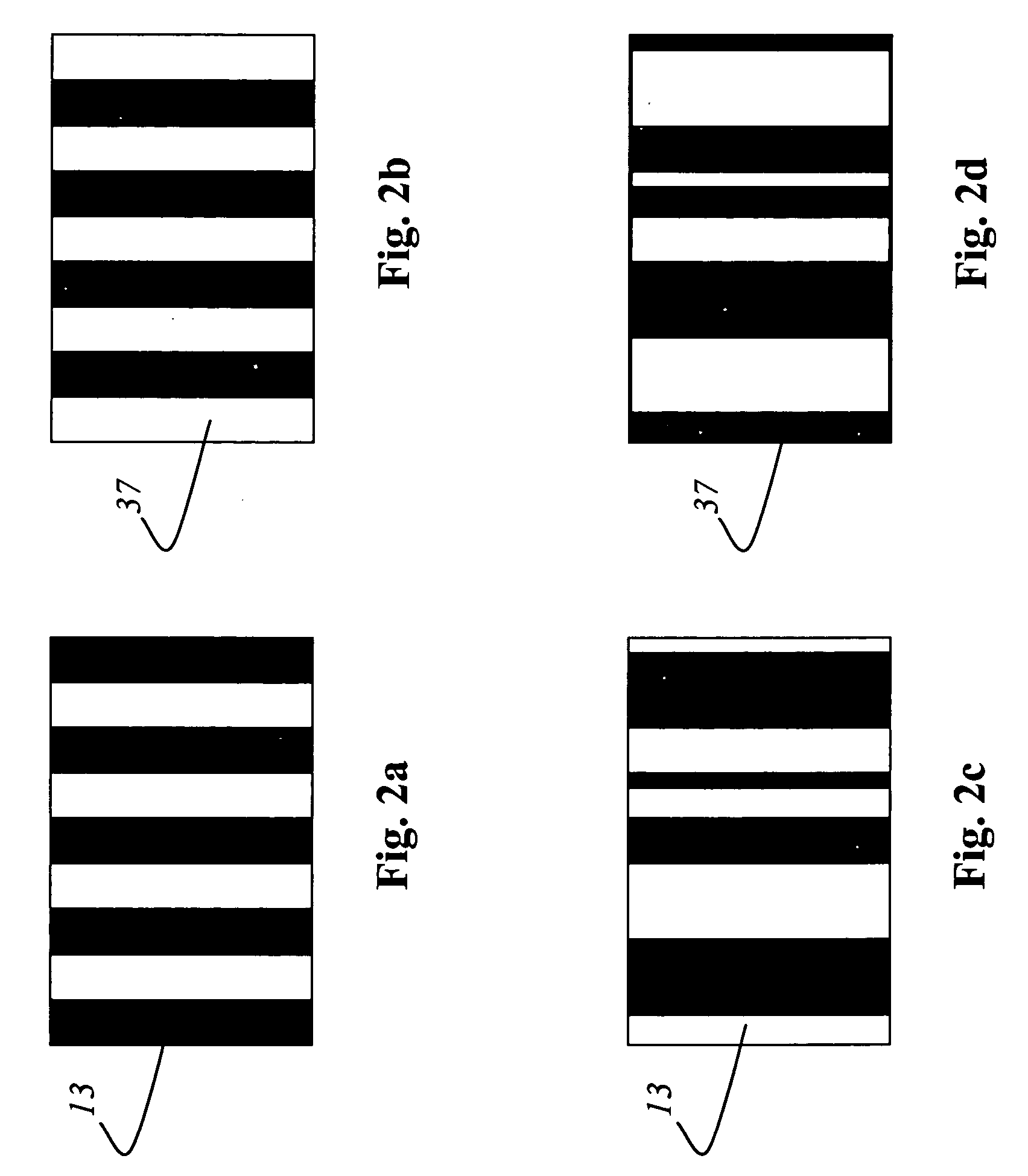
[0037] The microscope contains a spectral filter 5 that removes from illuminating light beam 1 the light components of the illuminating light that comprise wavelengths within the detection spectral region. For that purpose, the light is spatially spectrally split using a first grating 9, and then focused with first lens 11 onto a mask 13 which removes the spectral components that lie within the detection spectral region. Grating 9 and first mask 13 are located in the focal planes of lens 11 in a 4f arr...


PUM

PropertyMeasurementUnit
microscopyaaaaaaaaaa
wavelengthsaaaaaaaaaa
confocal scanning microscopeaaaaaaaaaa

Abstract

A method for microscopy includes generating pulsed illuminating light including wavelengths in a spectral region. A detection spectral region within the spectral region is defined. Using a dynamically controllable mask, light components of the illuminating light that comprise wavelengths within the detection spectral region are influenced. A specimen is illuminated with the influenced illuminating light. Detection light proceeding from the specimen within the detection spectral region is detected.

Description

CROSS REFERENCE TO RELATED APPLICATIONS [0001] This is a continuation of application Ser. No. 10 / 601,804, filed Jun. 23, 2003, which claims priority to German patent application 102 28 374.5. The subject matter of both of these applications is hereby incorporated by reference herein.FIELD OF THE INVENTION [0002] The invention concerns a method for microscopy. The invention furthermore concerns a microscope and a confocal scanning microscope. BACKGROUND OF THE INVENTION [0003] For the investigation of biological specimens, it has been usual for some time to prepare the specimen using optical markers, in particular fluorescent dyes. Often, for example in the field of genetic research, several different fluorescent dyes are introduced into the specimen and become attached specifically to certain specimen constituents. From the fluorescence properties of the prepared specimen conclusions can be drawn, for example, as to the nature and composition of the specimen or the concentration of ...

Claims


Application Information

Patent Timeline
Patent Type & Authority Applications(United States)
IPC IPC(8): G01N21/64G01J3/12G02B21/00
CPCG01J3/0229G01J2003/1282G01N21/6458G02B21/0004G02B21/0032G02B21/0064G02B21/0068G02B21/008
Inventor SEYFRIED, VOLKER
Owner LEICA MICROSYSTEMS CMS GMBH
Why Eureka
Try Eureka