Demagnetization circuit for using in push-pull circuit

a push-pull circuit and demagnetization circuit technology, applied in the direction of power conversion systems, instruments, dc-dc conversion, etc., can solve the problems of complex circuit design, reduced design complexity and manufacturing cost, and possible short circuit, so as to reduce design complexity and manufacture cost, and reduce the effect of remanent magnetization of the transformer

Inactive Publication Date: 2006-05-11
SYSGRATION
View PDF1 Cites 4 Cited by
  • Summary
  • Abstract
  • Description
  • Claims
  • Application Information

AI Technical Summary

Benefits of technology

[0009] The second object of the present invention provides a demagnetization circuit for using in a push-pull circuit. The demagnetization circuit of the present invention efficiently removes the remanent magnetization of the transformer so as to prevent the transformer from being short.
[0010] Another object of the present invention provides a demagnetization circuit for using in a push-pull circuit. The demagnetization circuit is directly designed in the push-pull circuit and thus the design complexity and manufacture cost are reduced.
[0011] Another object of the present invention provides a demagnetization circuit for using in a push-pull circuit. The demagnetization circuit of the present invention removes the remanent magnetization of the transformer so as to prevent the output waveform from generating burst and distortion.

Problems solved by technology

At this time, MOSFET cannot regulate the voltage and the magnetic core of the transformer is saturated, and the internal resistance will approach zero which makes a huge current and generates a burst or causes distortion at the output of the transformer (referring to FIG. 1) and thus the circuit is possible short.
However, because the push-pull circuit uses the characteristic of MOSFET, i.e. fast switching on / off, remanent magnetization energy will be generated without loop for releasing as MOSFET off, and thus another demagnetization design is needed; if another demagnetization manner is disposed in the uninterruptible power system, the whole circuit design will be complicated and the cost will relatively increase.

Method used


Image

  • Demagnetization circuit for using in push-pull circuit
  • Demagnetization circuit for using in push-pull circuit
  • Demagnetization circuit for using in push-pull circuit

Examples


Embodiment Construction

[0021] Now, the present invention will be described more specifically with reference to the following embodiments. It is to be noted that the following descriptions of preferred embodiments of this invention are presented herein for purpose of illustration and description only; it is not intended to be exhaustive or to be limited to the precise form disclosed.

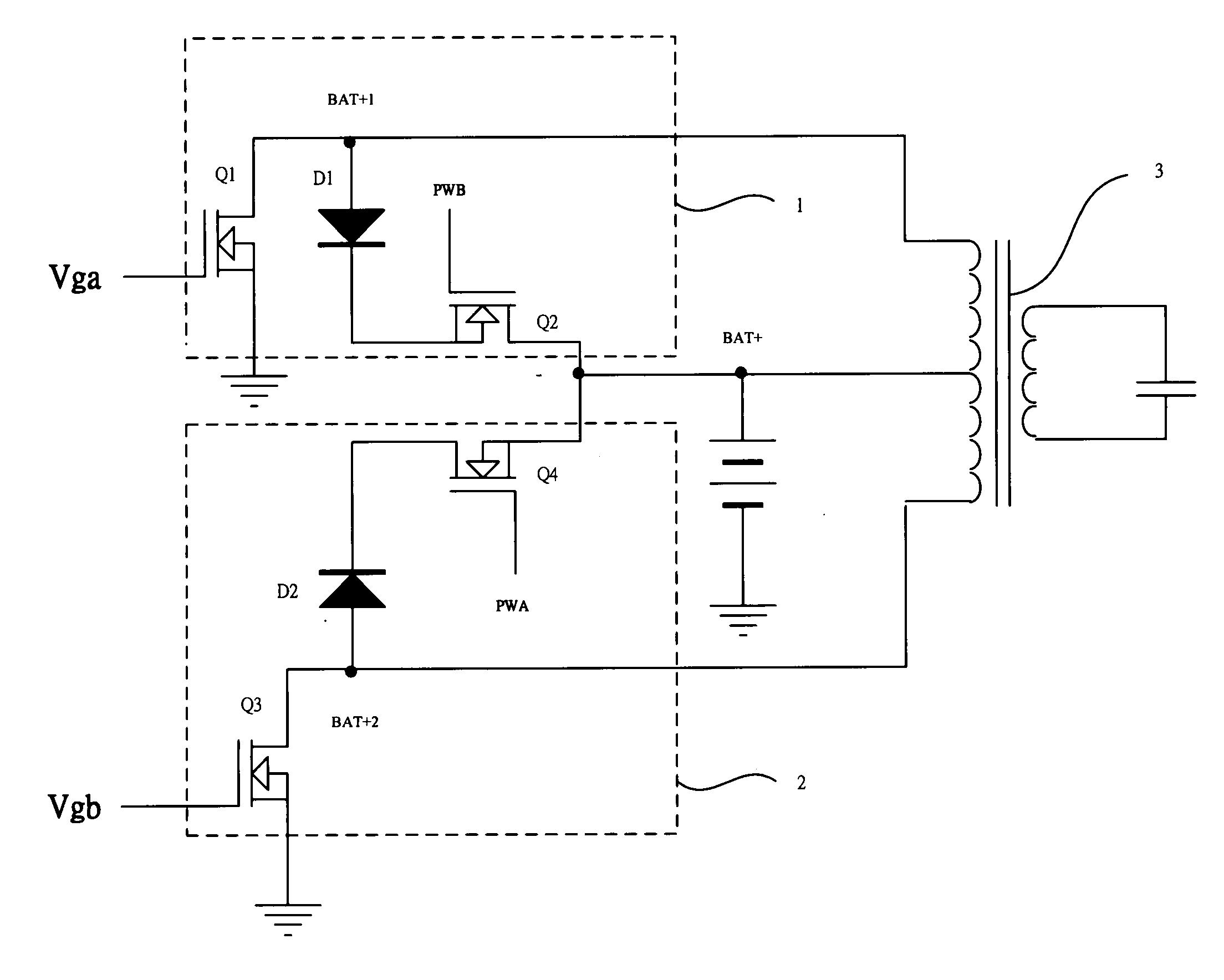
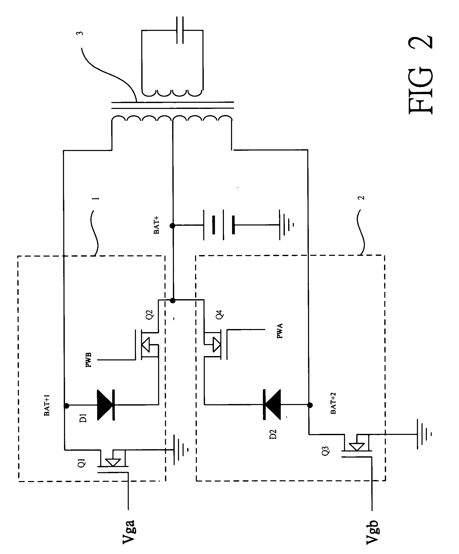
[0022] Referring to FIG. 2, which show a schematic diagram of a circuit of the present invention. The present invention relates to a demagnetization circuit for using in a push-pull circuit, the demagnetization circuit comprises:

[0023] a positive-half-period driving circuit 1 comprises a first transistor Q1 and a second transistor Q2 for modulating pulse width; a diode D1 for conduction;

[0024] a negative-half-period driving circuit 2 comprises a first transistor Q3 and a second transistor Q4 for modulating pulse width; a diode D2 for conduction; and

[0025] a transformer 3 connects to the positive-half-period driving circuit ...


PUM


Abstract

A demagnetization circuit that is used in a push-pull circuit, when the positive-half-period circuit is on and the negative-half-period circuit is off, a pulse width modulation signal (Vga) at MOSFET side of the positive-half-period circuit is inversed (PWB) and then transmitted into negative-half-period demagnetization circuit, which renders the negative-half-period demagnetization circuit conducted and short so that the demagnetization is operated during the positive-half-period; when the negative-half-period circuit is operating, a pulse width modulation signal (Vgb) at MOSFET side of the negative-half-period circuit is inversed (PWB) and then transmitted into positive-half-period demagnetization circuit, and the above circuits are alternatively switched and short for demagnetization so as to prevent the transformer from generating remanent magnetization.

Description

BACKGROUND OF THE INVENTION [0001] 1. Field of the Invention [0002] A demagnetization circuit that is used in a push-pull circuit, when the positive-half-period circuit is on and the negative-half-period circuit is off, a pulse width modulation signal (Vga) at MOSFET side of the positive-half-period circuit is inversed (PWB) and then transmitted into negative-half-period demagnetization circuit, which renders the negative-half-period demagnetization circuit conducted and short so that the demagnetization is operated during the positive-half-period; when the negative-half-period circuit is operating, a pulse width modulation signal (Vgb) at MOSFET side of the negative-half-period circuit is inversed (PWB) and then transmitted into positive-half-period demagnetization circuit, and the above circuits are alternatively switched and short for demagnetization so as to prevent the transformer from generating remanent magnetization. [0003] 2. Description of Related Art [0004] As technology ...

Claims


Application Information

Patent Timeline
Patent Type & Authority Applications(United States)
IPC IPC(8): H02M3/335
CPCH02J3/382H02M3/33569H02J2300/20H02J3/381
Inventor CHANG, CHUN-CHING
Owner SYSGRATION
Why Eureka
Try Eureka