Optical fiber for fiber laser, fiber laser, and laser oscillation method

a technology of optical fiber and fiber laser, which is applied in the direction of cladded optical fiber, instruments, optical elements, etc., can solve the problems of destroying the core region b, unable to obtain a laser beam with high quality, and current fiber lasers are limited to oscillation of several hundreds of watts, so as to achieve selective oscillation and high quality

Inactive Publication Date: 2006-05-11
HITACHI METALS LTD
View PDF11 Cites 25 Cited by
  • Summary
  • Abstract
  • Description
  • Claims
  • Application Information

AI Technical Summary

Benefits of technology

[0038] The effects of the invention are as follows.
[0039] (2) Since it is possible to selectively oscillate only the lowest mode without suppressing the higher mode b...

Problems solved by technology

However, when one attempts to realize oscillation of a further higher output power, the power density within the core region 42 will be extremely high, thereby possibly destroying the core region 42.
Thus, current fiber lasers are limited to oscillation of several hundreds watts.
However, when the core region is enlarged, a multi-mode oscillation will appear inst...

Method used


Image

  • Optical fiber for fiber laser, fiber laser, and laser oscillation method
  • Optical fiber for fiber laser, fiber laser, and laser oscillation method
  • Optical fiber for fiber laser, fiber laser, and laser oscillation method

Examples


first embodiment

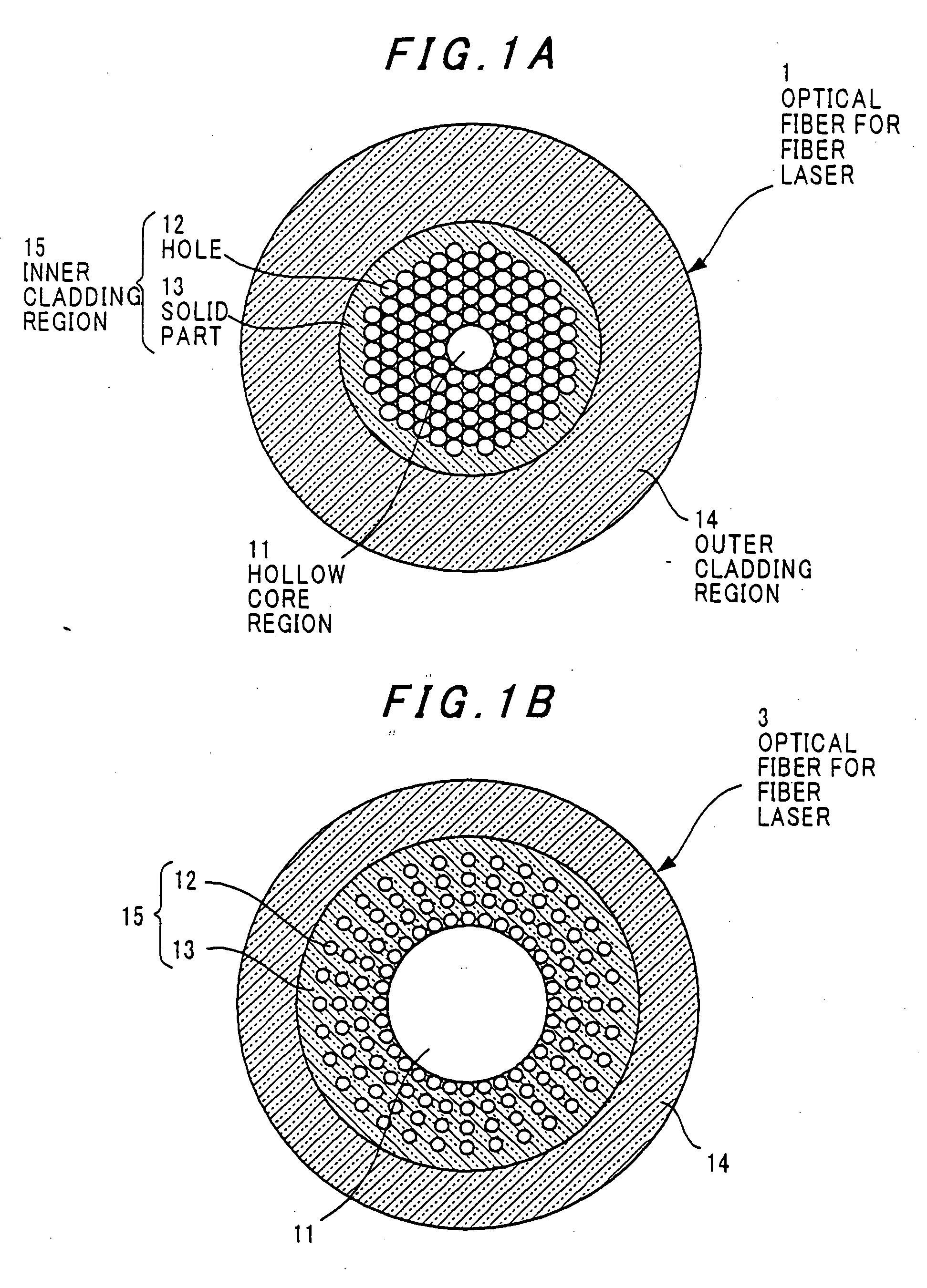
[0047]FIG. 1A is a transversal cross-sectional view showing an optical fiber for a fiber laser in the invention.

[0048] The optical fiber for the fiber laser of the embodiment is made of a hollow-core optical fiber having a hollow core region.

[0049] Referring to FIG. 1A, an optical fiber 1 for a fiber laser comprises a hollow core region 11, an inner cladding region 15 surrounding the hollow core region 11, and an outer cladding region 14 surrounding the inner cladding region 15. Further, the inner cladding region 15 comprises a plurality of holes 12 extending in a longitudinal direction of the optical fiber 1 for the fiber laser (fiber 1) and surrounding the hollow core region 11.

[0050] In FIG. 1A, the holes 12 are disposed around the hollow core region 11 so as to attain generally the closest packing. It is sufficient that the diameter of the hollow core region 11 is larger than the wavelength of the laser beam, and is suitably set in accordance with a power of the laser beam and...

second embodiment

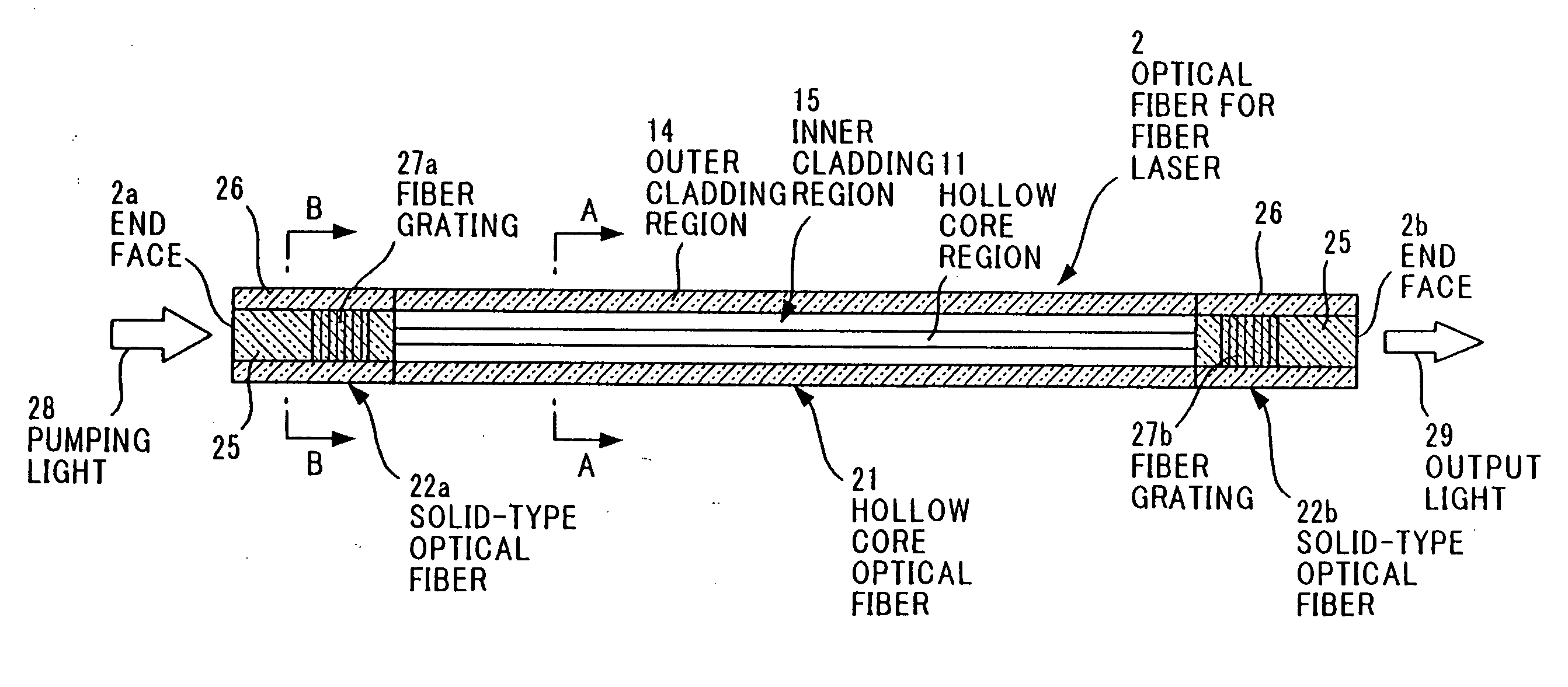
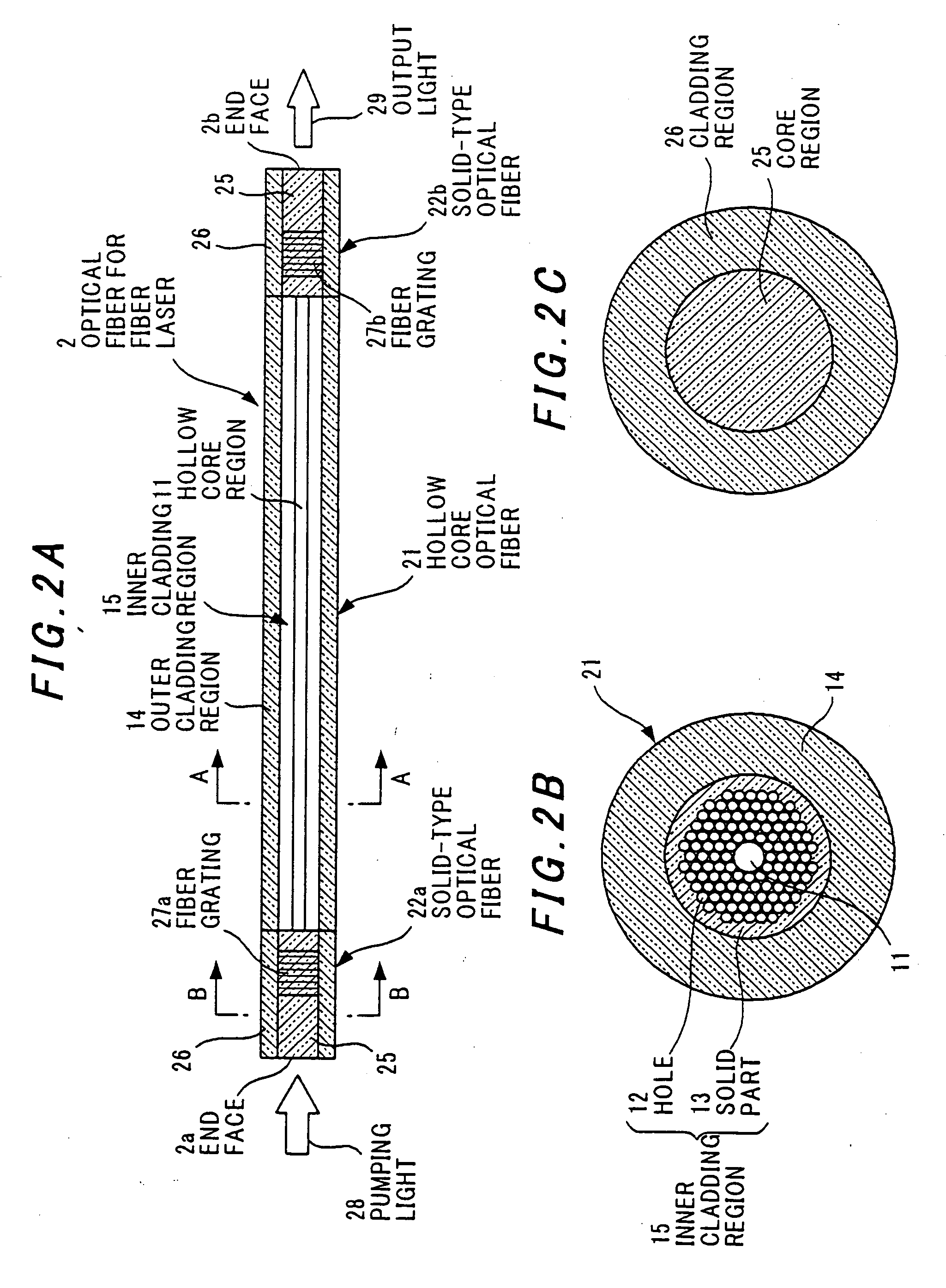
[0060]FIG. 2 shows the invention for obtaining laser oscillation.

[0061] Referring to FIG. 2, in an optical fiber 2 for fiber laser according to the second embodiment, solid-type optical fibers 22a, 22b are respectively disposed at both ends of a hollow-core optical fiber 21 having a structure similar to that of the optical fiber 1 for fiber laser according to the first embodiment.

[0062] In the hollow-core optical fiber 21, a hollow core region 11 and a plurality of holes 12 surrounding the hollow core region 11 are formed in a manner similar to that of the first embodiment. A band gap is formed in this hollow-core optical fiber 21 by adjustment of the bore diameter of the holes 12 and the interval between the holes 12 in accordance with the wavelength of the laser oscillation.

[0063] Short solid-type silica optical fibers 22a, 22b are respectively connected by fusion splice to both ends of the hollow-core optical fiber 21. This short solid-type silica optical fiber 22 includes a co...


PUM


Abstract

An optical fiber for a fiber laser has: a hollow core region; an inner cladding region having a plurality of holes that extend in a longitudinal direction of the optical fiber and surround the hollow core region; and an outer cladding region that surrounds the inner cladding region. The inner cladding region has a solid part that is made of a glass material into a part or all of which a rare earth element is doped, and the outer cladding region has a refractive index lower than that of the solid part of the inner cladding region.

Description

[0001] The present application is based on Japanese patent application No. 2004-314223, the entire contents of which are incorporated herein by reference. BACKGROUND OF THE INVENTION [0002] 1. Field of the Invention [0003] This invention relates to an optical fiber for a fiber laser that oscillates a high-output laser beam and is useful for laser processing, medical use and the like. Also, this invention relates to a fiber laser and a laser oscillation method using the optical fiber. [0004] 2. Description of the Background Art [0005]FIG. 3 shows an optical fiber 41 with a double cladding structure used for a conventional fiber laser. [0006] A core region 42 is doped with a rare earth element such as neodymium (Nd), ytterbium (Yb), erbium (Er) and thorium (Th). The core region 42 is surrounded by an inner cladding region 44, and the inner cladding region 44 is surrounded by an outer cladding region 45. [0007] In operation, pumping light 46 is incident into the optical fiber 41, propa...

Claims


Application Information

Patent Timeline
IPC IPC(8): H01S3/30G02B6/032
CPCG02B6/02328G02B6/02347G02B6/02357G02B6/02361H01S3/06708H01S3/0672H01S3/06729H01S3/06741H01S3/0675
Inventor HONGO, AKIHITO
Owner HITACHI METALS LTD
Why Eureka
Try Eureka