Decorative laminate board

a technology of decorative laminate and laminate board, which is applied in the field of decorative laminate board, can solve the problems of wear on the tools used for milling these boards into user-friendly formats, undesired whitening effect on the machined edge of wear layer and decor layer, and microscopic cracks during milling. achieve the effect of quick blunting the tools

Inactive Publication Date: 2006-05-11
PERGO
View PDF6 Cites 78 Cited by
  • Summary
  • Abstract
  • Description
  • Claims
  • Application Information

AI Technical Summary

Benefits of technology

[0021] It is known by the one skilled in the art of making thermosetting laminate the milling operations, besides quickly blunting the tools, also have the problem that whitening effect is created in the milling zone. This effect is in most cases undesired. It will, by utilizing the steps described in the present invention, be possible to achieve well defined embossing without blunting tools and not leaving any white marks or other imperfections as discussed previously.
[0022] The decorative laminate board of the present invention is foremost used for floor panels, floor tiles, wall panels and ceiling panels. The embossing herein described is suitable for simulating ship deck flooring and grouted tile flooring. Also other types of embossing like logotypes or other patterns can easily be made. It is also very easy to create nonlinear patterns of for example grout lines if a more rugged and rustic design pattern is desired.

Problems solved by technology

The hard particles will of course cause wear on the tools used for milling these boards into user friendly formats.
It is also known that cutting tools will cause an undesired whitening effect on the machined edge of a wear layer and decor layer.
As the wear layer normally is very hard and a bit brittle, microscopic cracks will sometimes occur during the milling.
Another problem related to this, is when smaller pieces of the edge is chipped away, due to its brittle nature, during the machining operation.
Yet another, but unrelated cause to the problem, is when subjacent layers of the laminate are white or have bright colors.
There is accordingly a problem where machining like edge trimming and embossing in the surface is desired.

Method used


Image

  • Decorative laminate board
  • Decorative laminate board
  • Decorative laminate board

Examples


Embodiment Construction

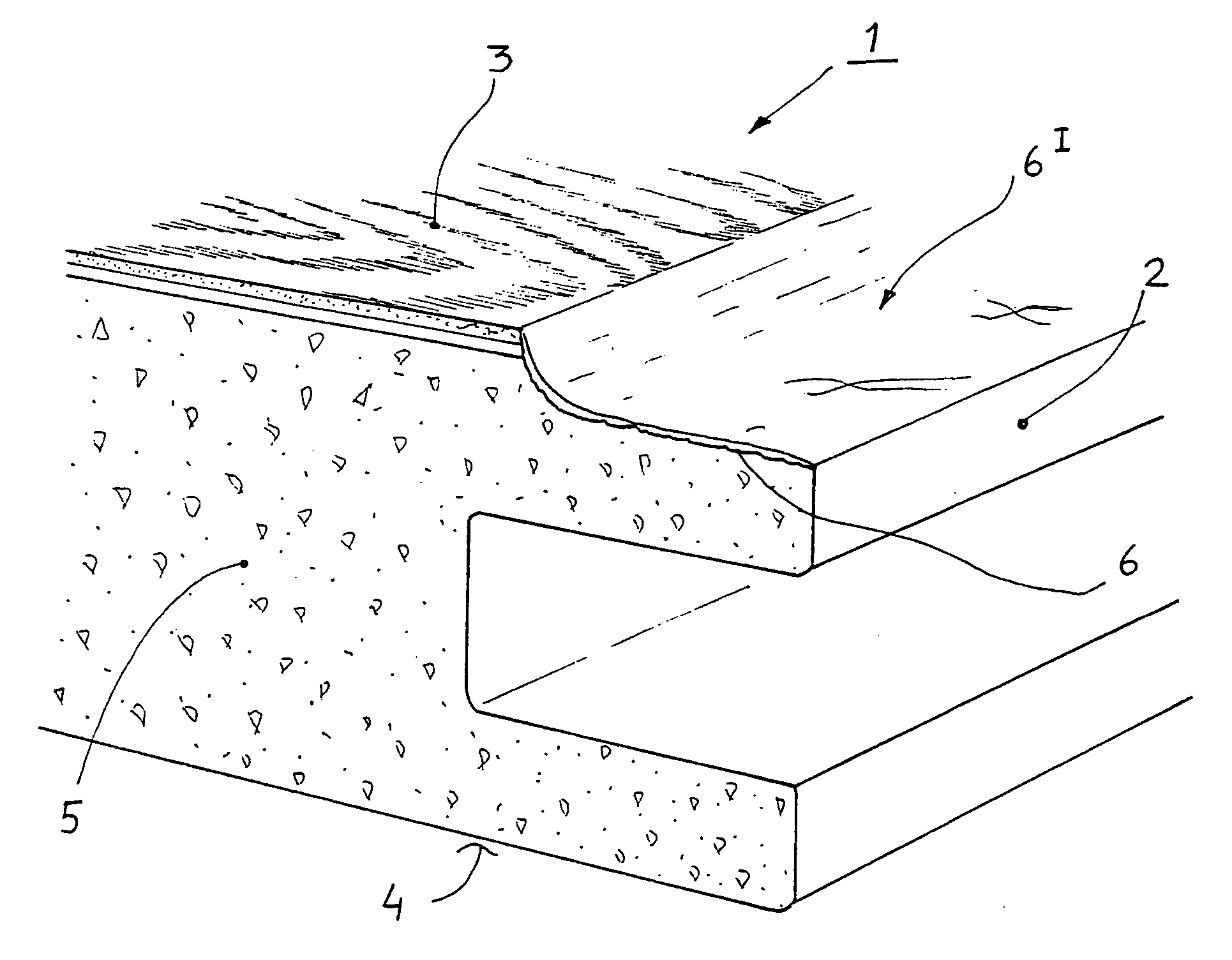
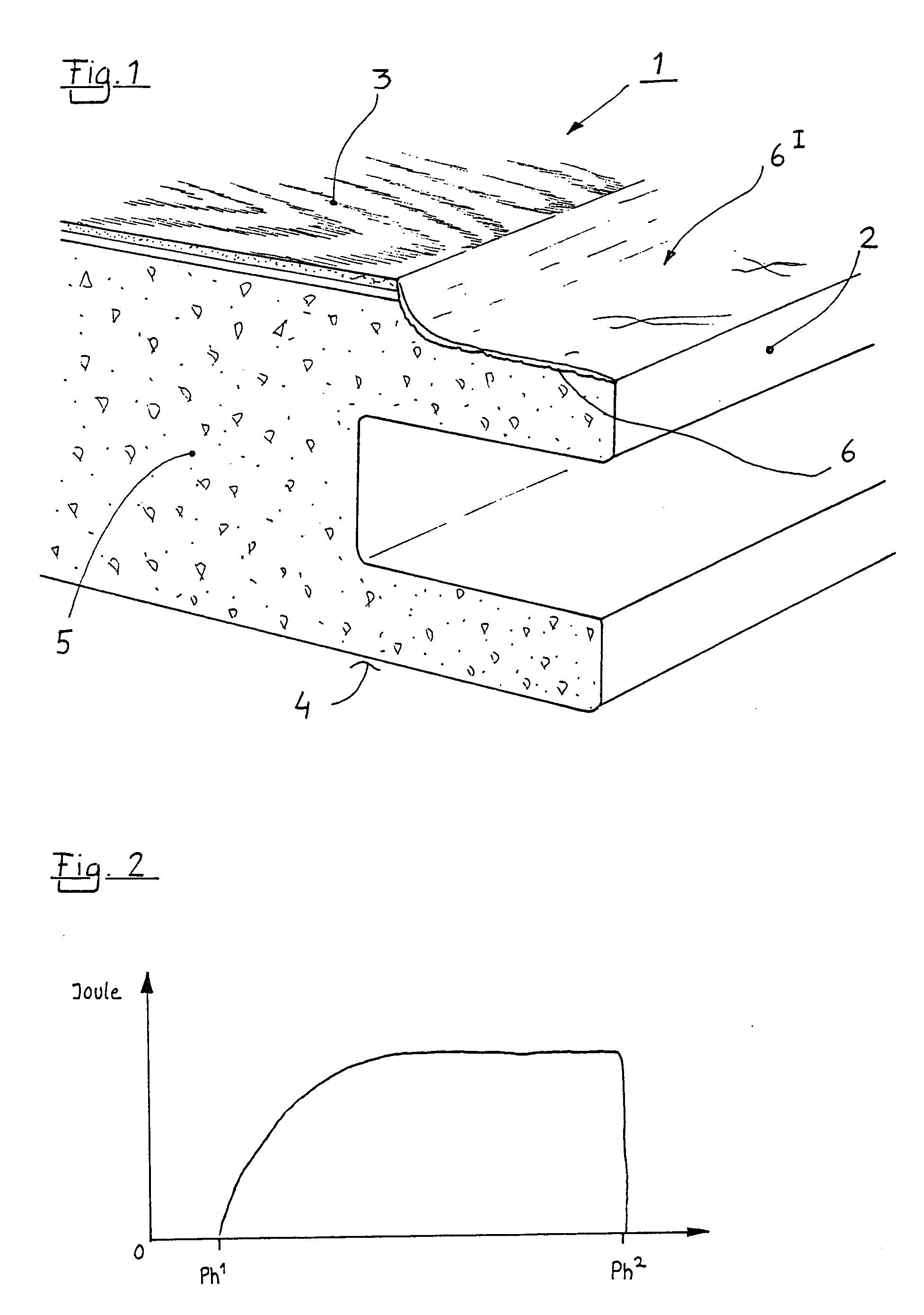
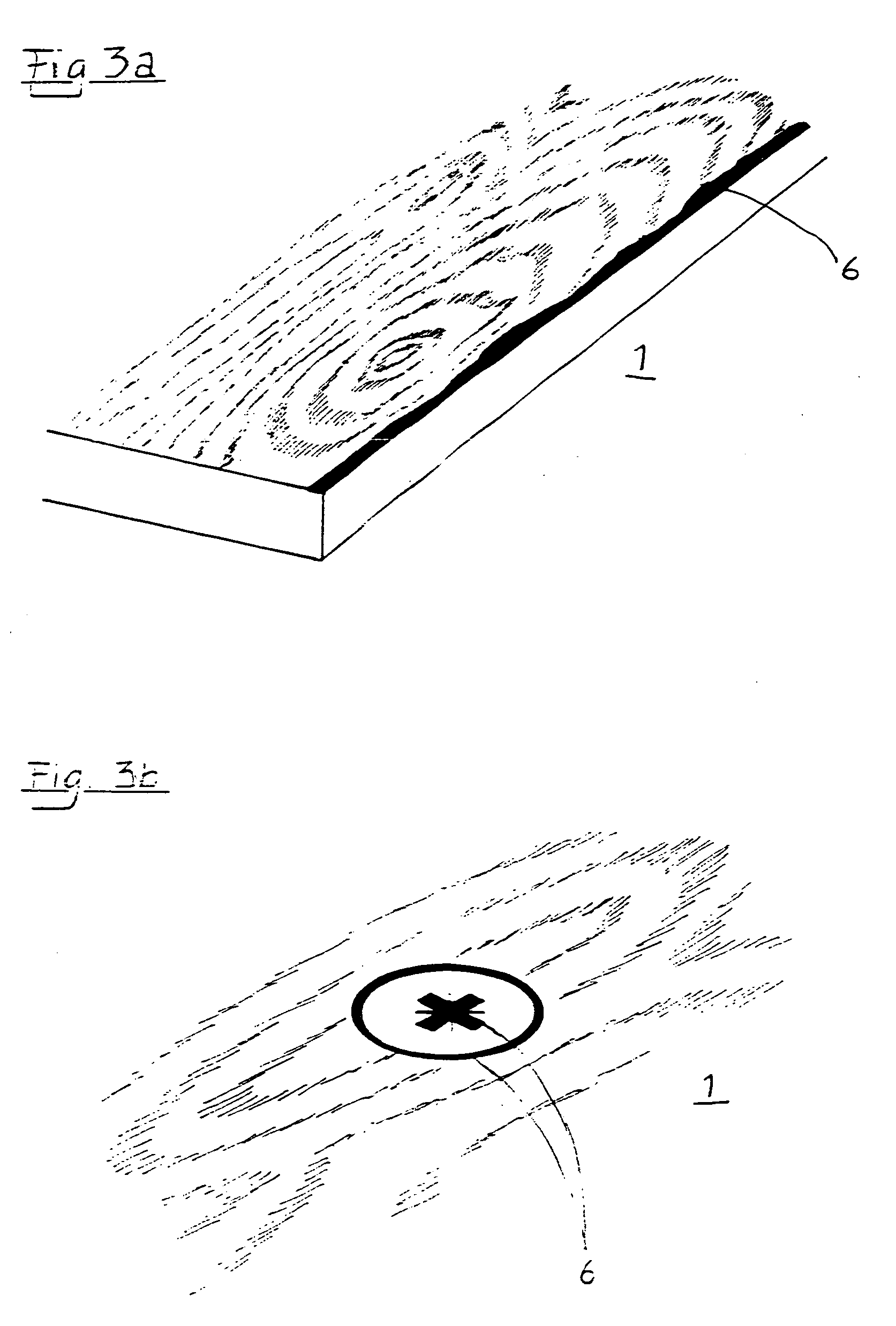
[0027]FIG. 1 shows, in cross-section portions of a decorative laminate board 1 having edges 2, a decorative upper laver 3 and a rear layer 4. The decorative laminate 1 board includes a base layer 5, an intermediate decor layer and a wear laver which comprises cellulose and thermosetting resin. Predetermined portions of the decorative upper layer 3 is provided with an embossed 6 surface through means of a laser beam. Portions of the decorative upper layer 3 is removed by being burnt away by the laser beam. The laser beam was emanating two laser emitters. The embossed 6 surface was charred after the operation.

[0028] As best shown in FIG. 2 the laser beam had a first and second periphery Ph1 and Ph2 respectively and an intermediate zone. An energy profile within the zone between the first and second periphery was adjusted to create an embossing 6 effect having a radius towards the untreated portions of the decorative upper layer 3.

[0029] Referring again to FIG. 1 where the uppermost ...


PUM

PropertyMeasurementUnit
particle sizeaaaaaaaaaa

Abstract

A decorative laminate board having edges, a decorative upper layer and a rear layer. The decorative laminate board includes at least a base layer, an intermediate decor layer and a wear layer where at least one of said layers comprises polymers. Predetermined portions of the decorative upper layer is provided with an embossed surface through means of a laser beam.

Description

BACKGROUND OF THE INVENTION [0001] 1. Field of the Invention [0002] The present invention relates to a decorative laminate board with a surface structure achieved through means of laser beam. [0003] 2. Description of Related Art [0004] Products coated with thermosetting laminates are frequent today. They are foremost used where the demand for abrasion resistance is high, but also where resistance towards different chemicals and moisture is required. As an example of such products floors, floor beadings, table tops, work tops and wall panels can be mentioned. [0005] The abrasion resistance is usually achieved by adding very small hard particles like silicon carbide to the wear layer. Such a wear laver may also include cellulose and a thermosetting resin like melamine formaldehyde resin. Also UV-curing lacquers are used. [0006] The hard particles will of course cause wear on the tools used for milling these boards into user friendly formats. It is also known that cutting tools will ca...

Claims


Application Information

Patent Timeline
Patent Type & Authority Applications(United States)
IPC IPC(8): D06N3/00
CPCB32B3/06Y10T428/24438B32B5/26B32B21/02B32B21/10B32B21/14B32B27/12B32B2250/03B32B2255/02B32B2255/26B32B2260/023B32B2260/046B32B2262/062B32B2419/04B44C1/228B44C5/043E04F15/02E04F15/02033Y10T428/195Y10T428/24777B32B3/30
Inventor SMITH, PATRICK
Owner PERGO
Why Eureka
Try Eureka