Epicardial heartwire, chest tube with epicardial heartwire, and method of use

Active Publication Date: 2006-05-11
YACOUBIAN VAHE S
View PDF17 Cites 7 Cited by
  • Summary
  • Abstract
  • Description
  • Claims
  • Application Information

AI Technical Summary

Benefits of technology

[0017] Another advantage of the invention is that the chest tube can incorporate the ground pole to the temporary heartwire.
[0018] Further, since the wires are separable from the chest tube it becomes possible to remove the chest tube first, leaving the heartwire(s) in place for continued use. In 90% of cases, both chest tubes and pacing wires are used and can be removed together, at the same time. In some patients, however, the pacing wires might need to stay for few more days after chest tube removal.
[0019] Additional advantages of the invention are as follows: It eliminates any necessity to leave loops of wire on or near the surface of the heart, by combining the chest tube and the heartwire together so as to permit shortening the heartwire length. It does not require the pacing wire to be in a myocardial tunnel, but rather lets the wire sit on the epicardium (the outer covering of the heart) and prevents its dislodgment by suturing a Teflon or other material pledget on the myocardium over the pacing wire and tie. It may permit all cardiac surgery patients to have pacing wires for at least 1-2 days, so that they can be paced immediately if the need arises. Once the chest tube is removed, the pacing wires come out together

Problems solved by technology

A problem that occurs sometimes is that, during the pullout process, the myocardial tissue is injured or disturbed and starts bleeding again.
Also, since epicardial heartwires are normally placed underneath the skin in the form of a loop, the loop of a w

Method used


Image

  • Epicardial heartwire, chest tube with epicardial heartwire, and method of use
  • Epicardial heartwire, chest tube with epicardial heartwire, and method of use
  • Epicardial heartwire, chest tube with epicardial heartwire, and method of use

Examples


first embodiment

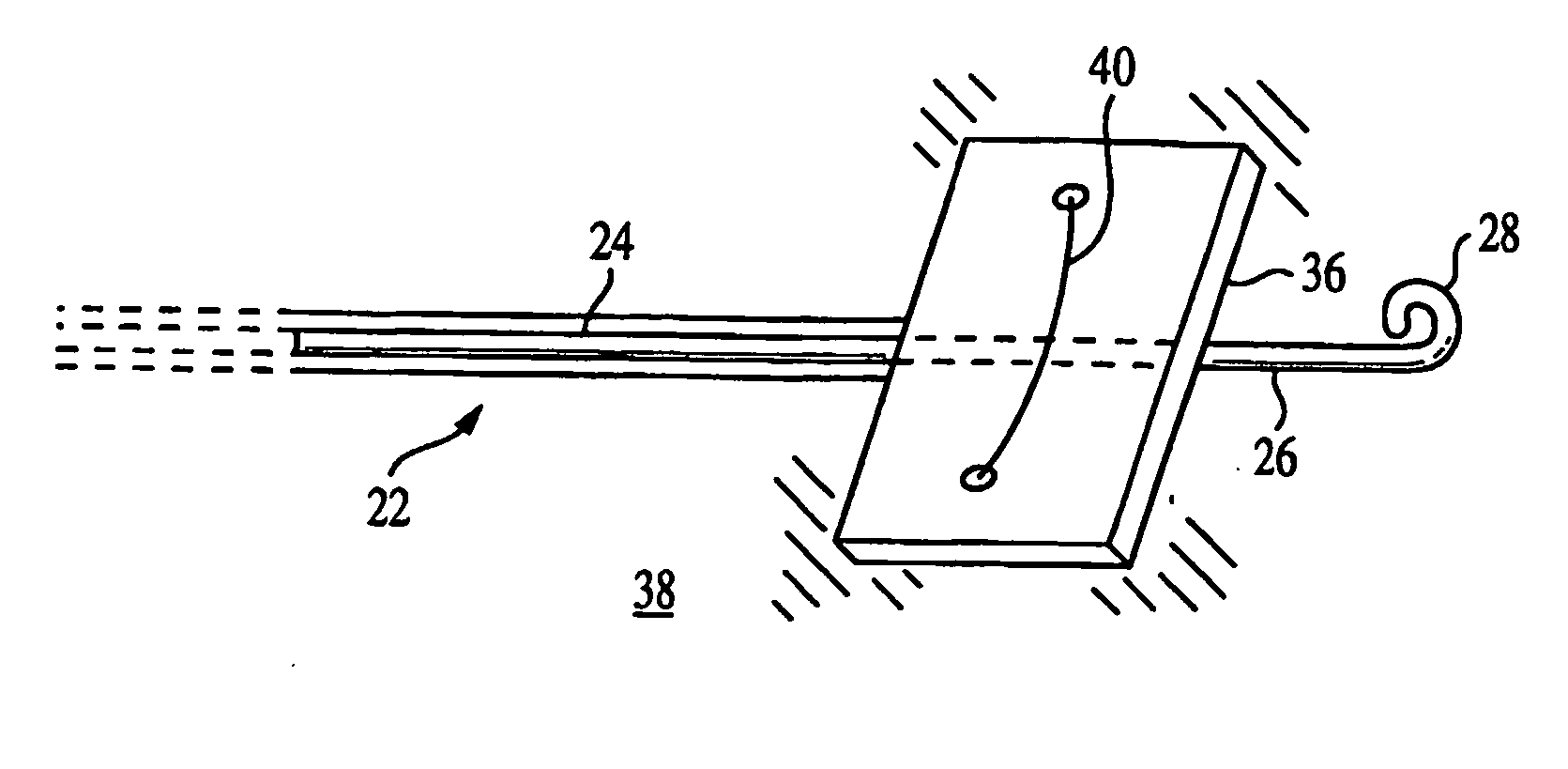
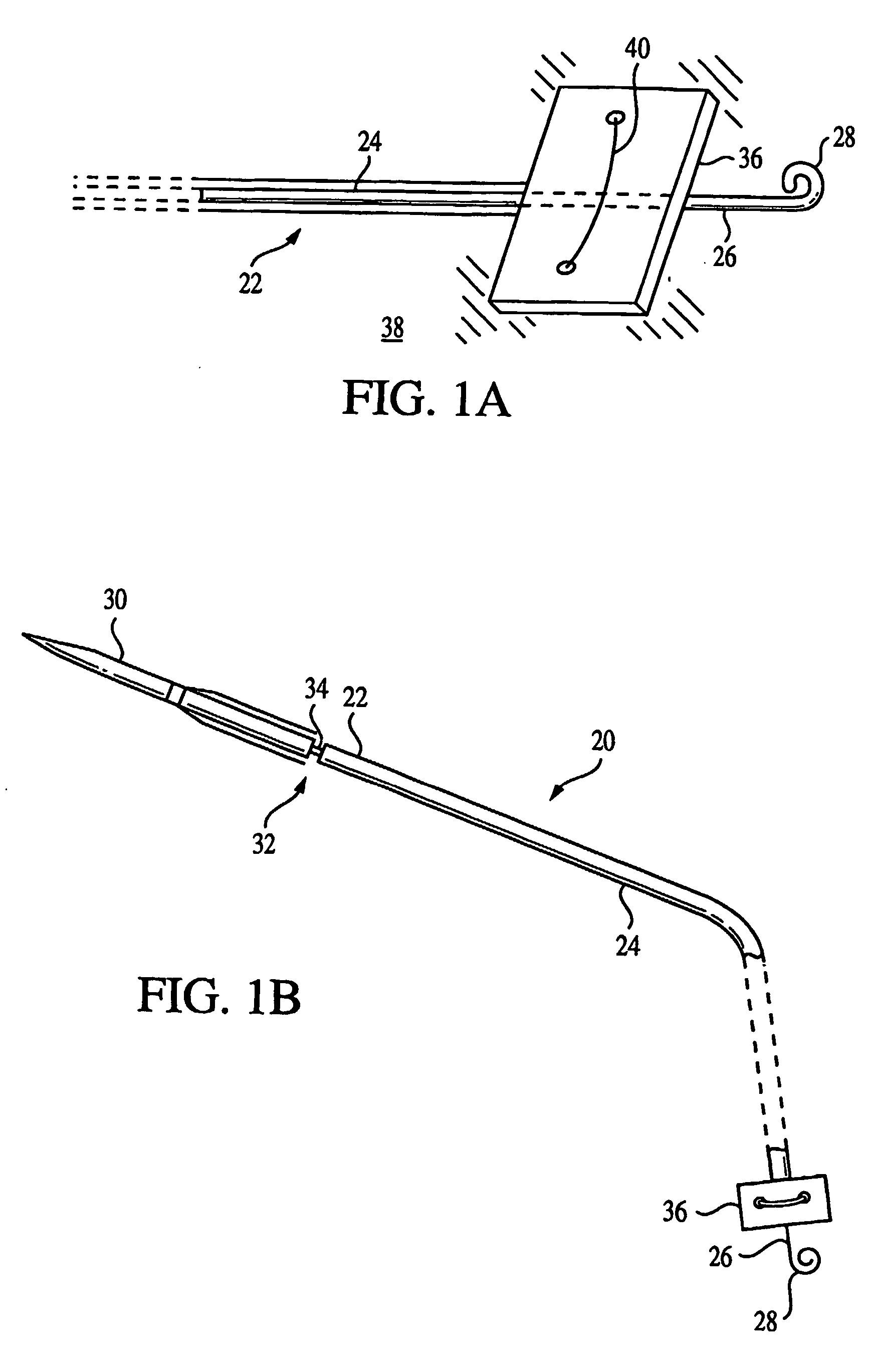
[0032]FIGS. 1A and 1B show an epicardial heartwire 20 according to the invention, having a proximal end 22 and a distal end 26. Biocompatible insulation 24 covers most of the wire. At the opposite end of the heartwire is a distal end or pole 26 where the wire is bare. An insulated pigtail 28 which comprises for example a coiled silastic or silicone or other insulating material is attached to the distal pole by any convenient means. Another atraumatic structure such as tines, hooks or a coil may be substituted for the pigtail 28.

[0033]FIGS. 1A and 1B also show a conventional pledget 36. The pledget is shown connected to the myocardium of a patient 38 in conventional fashion, for example by a Prolene suture 40. The distal pole 26 of the heartwire 20 is placed underneath the pledget 36, between the pledget and the myocardium, for providing electrical contact for pacing. The pigtail 28 extends under and past the pledget and holds it in place there.

[0034] The heartwire 20 may be attache...

third embodiment

[0044]FIGS. 5 and 6 show the invention. A chest tube 40 has a first wire 42b and a second wire 44b fixed to the chest tube 40 by a pacing system fixation wing 58. The wing 58 is in turn fixed to the chest tube by a thin plastic film 60 or another suitable means, which is easily removable if it is desired to remove the chest tube without removing the heartwires.

[0045] As seen in FIG. 5, the first wire 42b need not be fixed to the distal end 54 as described above. It is shown free of the distal end 54 in FIG. 6. If it is initially fixed to the distal end 54, then it is separated at the time of use and placed in the position shown in FIG. 6.

[0046] In the embodiment of FIGS. 5-6, the wires 42a, 44b pass through a longitudinal lumen formed in the fixation wing 58. However, they may be adhered to the fixation wing 58 in any other suitable way as well.

[0047] This embodiment may for example be used for ventricular pacing by connecting the short ground (+) wire 44b to the ground (+) pole o...


PUM


Abstract

A heartwire comprises a wire having a proximal end and a distal end, at least part of the distal end being conductive so as to be usable in heart stimulation; and attached to said distal end, an end structure adapted for non-invasively maintaining the distal end in position adjacent the heart. The end structure may comprise an irregular or three-dimensional, atraumatic structure adapted for engaging a surgical material secured to the heart, for maintaining said heartwire in position relative to said surgical material. The surgical material may be a pledget, and the end structure may comprise at least one of a pigtail, a hook, a tine and a suture sized and shaped for engaging the pledget so as to maintain the heartwire in position. The heartwire may comprise a second wire having a corresponding distal end structure and may be a bipolar heartwire. An arrangement for stimulating a heart may comprise the foregoing heartwire, in combination with a surgical material for being secured to the heart. The heartwire may be combined with and/or secured to a chest tube, and may be removable from the chest tube while still in position relative to the heart. A chest tube may also be combined with an anesthesia delivery tube and/or a wire for carrying cardiac output monitoring signals.

Description

CROSS-REFERENCE TO RELATED APPLICATIONS [0001] This application is based upon and claims priority of U.S. Provisional Patent Application 60 / 424,537 filed Nov. 7, 2002, the disclosures of which are incorporated by reference herein. It is also based on U.S. Provisional Application 60 / 350,710 filed Nov. 13, 2001, also incorporated by reference.BACKGROUND OF THE INVENTION [0002] 1. Field of the Invention [0003] The present invention relates to an epicardial heartwire (also called a temporary myocardial pacing wire or stimulation lead), a combination of a chest tube and an epicardial heartwire, and a method of using the same. [0004] 2. Related Art [0005] Conventionally, heartwires are positioned epicardially to the myocardium and stitched or passed through a myocardial tunnel. Typically, they stay between one and seven days in the myocardium, usually for 1-2 days, and preferably less than 7 days, after open-heart surgery. Before the patient is released from the hospital, the heartwires a...

Claims


Application Information

Patent Timeline
IPC IPC(8): A61N1/05A61M
CPCA61N1/0587
Inventor YACOUBIAN, VAHE S.
Owner YACOUBIAN VAHE S
Why Eureka
Try Eureka