Automated software-based hardware tracking system

a hardware tracking and software technology, applied in the field of automatic software-based hardware tracking systems, can solve the problems of no system currently exists to poll installed systems, written records are not available to service engineers, engineering and manufacturing, etc., to save time and parts costs, increase the likelihood, and save costs.

Inactive Publication Date: 2006-05-11
GE MEDICAL SYST GLOBAL TECH CO LLC
View PDF9 Cites 58 Cited by
  • Summary
  • Abstract
  • Description
  • Claims
  • Application Information

AI Technical Summary

Benefits of technology

[0012] One advantage of the present invention includes data mining and monitoring. In other words, information about board swap outs, replacements, configurations, and revision is readily available to engineering, providing crucial information that is stored in a centralized data warehouse (central database). This information is readily available to remote service engineers who may be trying to perform system fixes through an electronic remote connection.
[0013] Another advantage includes cost savings through tracking hardware replacements, thereby preventing replacement of the same board multiple times during system troubleshooting. Also, the system increases the likeli

Problems solved by technology

Determining the history of components replaced in a given system has been a long-standing issue for field engineers (FE) and service engineering in general.
The written records are not available to service engineers who may be trying to service the system remotely through a remote electronic connection.
Additionally, no system currently exists to poll the installed systems and obtain the configuration.
Marketing, engineering and manufacturing have no reliable method of tracking the hardware options

Method used


Image

  • Automated software-based hardware tracking system
  • Automated software-based hardware tracking system
  • Automated software-based hardware tracking system

Examples


Embodiment Construction

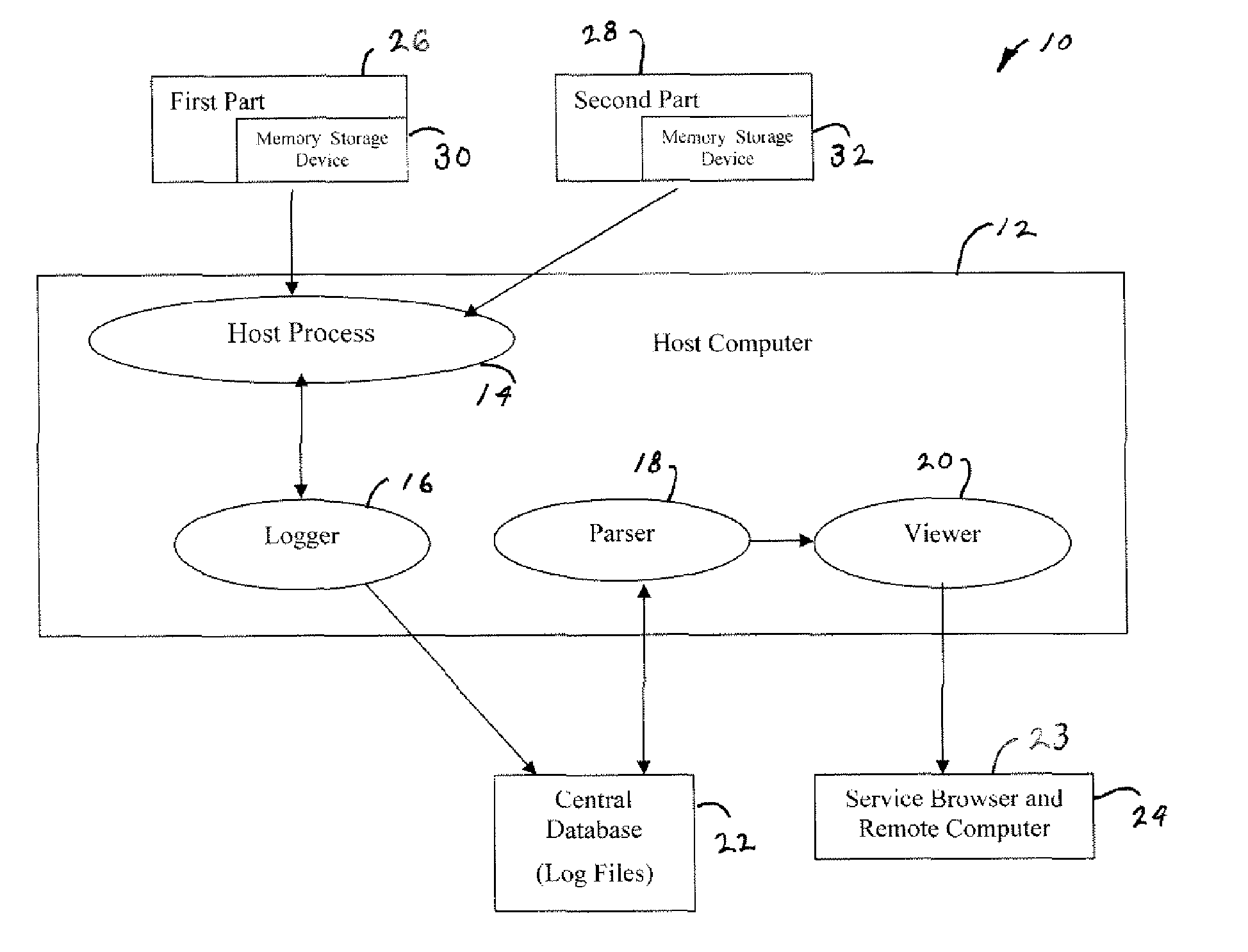
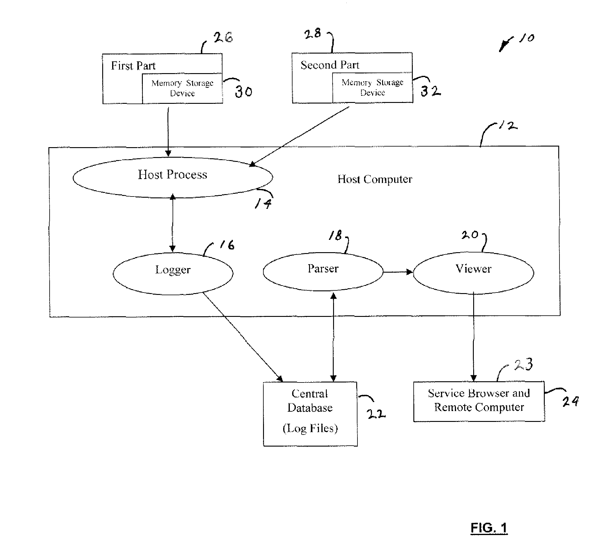
[0019] The present invention is illustrated with respect to a hardware tracking system 10, particularly suited for Magnetic Resonance machines. The present invention is, however, applicable to various other uses that may require hardware tracking, as will be understood by one skilled in the art.

[0020] Referring to FIG. 1, a hardware tracking system 10, including a host computer 12, is illustrated. The host computer 12 includes a host process unit 14, a logger 16, a parser 18, and a viewer 20. Coupled to the host computer 12 are: a central database 22 and a service browser 24 and remote computer 23.

[0021] Generally, the host computer 12 or real-time subsystem downloads information from a plurality of parts 26, 28 having individual memory storage devices 30, 32 and compares this with information stored in the central database 22. A user accesses the information in the central database 22 through the viewer 20 and parser 18 from the service browser 24.

[0022] The host computer 12 dow...


PUM


Abstract

A hardware tracking system includes memory storage devices on tracked parts containing unique serial numbers, part numbers, revision numbers, and firmware versions. At power up and after a reset, a host computer or real-time subsystem downloads this information and compares it to the information stored in a central database. Changes in data in a central database log file indicate a replacement or update of the component, which is then used to automatically update the database. Each change causes the generation of a new record having date and time information attached thereto. These records are scanned to determine the system evolution. They are also compared to an error log and diagnostic history information to generate a cause versus effect occurring during troubleshooting. The system also tracks and records the number of times a part is removed and re-inserted, indicating shot-gunning of the system by field engineers.

Description

TECHNICAL FIELD [0001] The present invention relates generally to hardware tracking systems, and more particularly, to an automated software based hardware tracking system. [0002] Determining the history of components replaced in a given system has been a long-standing issue for field engineers (FE) and service engineering in general. Field engineers require identification of previously replaced components when diagnosing long term intermittent problems. This is particularly true if multiple field engineers are working on the same system at different times. For service engineering organizations, the ability to track failures in the field is paramount to determining the mean time between failures (MTBF) of components. [0003] Additionally, tracking component revisions is crucial for tracking a failure to a particular board. This information aids in determining how often a part failed in the field in order to determine if a component failure or a design problem exists. Presently, the F...

Claims


Application Information

Patent Timeline
IPC IPC(8): G06F17/30
CPCG06Q10/087
Inventor CHIANESE, JOSEPH JAMESPETERSON, WILLIAMPETERSON, ERIKBYLSMA, PHILIP JAMES
Owner GE MEDICAL SYST GLOBAL TECH CO LLC
Why Eureka
Try Eureka