
Ethernet extension for the data center

a data center and Ethernet technology, applied in the field of Ethernet extension for the data center, can solve the problems of increasing complexity and cost of the connection, not desirable for servers to include significant storage capabilities, and many to be nearing physical limits, and achieve the effect of low latency and high reliability

Active Publication Date: 2006-05-11
CISCO TECH INC
View PDF99 Cites 71 Cited by
  • Summary
  • Abstract
  • Description
  • Claims
  • Application Information

AI Technical Summary

Benefits of technology

[0022] Active buffer management allows for both high reliability and low latency while using small frame buffers, even with 10 GB / s Ethernet. Preferably, the rules for active buffer management are applied differently for drop and no drop VLs. Some embodiments of the invention are implemented with copper media instead of fiber optics. Given all these attributes, I / O consolidation may be achieved in a competitive, relatively inexpensive fashion.

Problems solved by technology

However, with the increasing numbers of network devices within a data center, connectivity has become increasingly complex and expensive.
Moreover, it is not desirable for servers to include a significant storage capability.
Some envisioned a future speed of up to 1 Gb / s, but this was considered by many to be nearing a physical limit.
With 10 Mb / s Ethernet, there were the issues of half duplex and of collisions.
Ethernet was considered to be somewhat unreliable, in part because packets could be lost and because there could be collisions.
However congestion in a switch may cause Ethernet packets to be dropped and this is an undesirable feature for storage traffic.
Although these efforts met with some success, iSCSI has not become very popular: iSCSI has about 1%-2% of the storage network market, as compared to approximately 98%-99% for FC.
One reason is that the iSCSI stack is somewhat complex as compared to the FC stack.
TCP layer 715 is a necessary part of the stack because Ethernet layer 705 may lose packets, but yet SCSI layer 725 does not tolerate packets being lost.
However, TCP layer 715 is a difficult protocol to implement at speeds of 1 to 10 Gb / s.
It is well known that in recent years the cost of a typical server has decreased and its performance level has increased.
Because of the relatively low cost of servers and the potential problems that can arise from having more than one type of software application run on one server, each server is typically dedicated to a particular application.
However, because of the complexities of maintaining various types of connectivity (e.g., Ethernet and FC connectivity) with each server, each type of connectivity preferably being redundant for high availability, the cost of connectivity for a server is becoming higher than the cost of the server itself.
For example, a single FC interface for a server may cost as much as the server itself.
Therefore, when frames are dropped on an FC network, the system does not recover quickly and SCSI may take minutes to recover.
This would be prohibitively expensive.
Therefore, clustering of servers can add yet more complexity to data center networks.
However, Infiniband has a number of drawbacks.
Moreover, Infiniband has not been proven to work properly in the context of, e.g., a large enterprise's data center.
For example, there are no known implementations of Infiniband routers to interconnect Infiniband subnets.
While gateways are possible between Infiniband and Fibre Channel and Infiniband to Ethernet, it is very improbable that Ethernet will be removed from the datacenter.
Therefore, the cost of an Infiniband-based system would not be an alternative cost, but an additional cost.

Method used


Image

  • Ethernet extension for the data center
  • Ethernet extension for the data center
  • Ethernet extension for the data center

Examples


Embodiment Construction

[0058] Reference will now be made in detail to some specific embodiments of the invention including the best modes contemplated by the inventors for carrying out the invention. Examples of these specific embodiments are illustrated in the accompanying drawings. While the invention is described in conjunction with these specific embodiments, it will be understood that it is not intended to limit the invention to the described embodiments. On the contrary, it is intended to cover alternatives, modifications, and equivalents as may be included within the spirit and scope of the invention as defined by the appended claims. Moreover, numerous specific details are set forth below in order to provide a thorough understanding of the present invention. The present invention may be practiced without some or all of these specific details. In other instances, well known process operations have not been described in detail in order not to obscure the present invention.

[0059] The present inventi...


PUM


Abstract

The present invention provides methods and devices for implementing a Low Latency Ethernet (“LLE”) solution, also referred to herein as a Data Center Ethernet (“DCE”) solution, which simplifies the connectivity of data centers and provides a high bandwidth, low latency network for carrying Ethernet and storage traffic. Some aspects of the invention involve transforming FC frames into a format suitable for transport on an Ethernet. Some preferred implementations of the invention implement multiple virtual lanes (“VLs”) in a single physical connection of a data center or similar network. Some VLs are “drop” VLs, with Ethernet-like behavior, and others are “no-drop” lanes with FC-like behavior. Some preferred implementations of the invention provide guaranteed bandwidth based on credits and VL. Active buffer management allows for both high reliability and low latency while using small frame buffers. Preferably, the rules for active buffer management are different for drop and no drop VLs.

Description

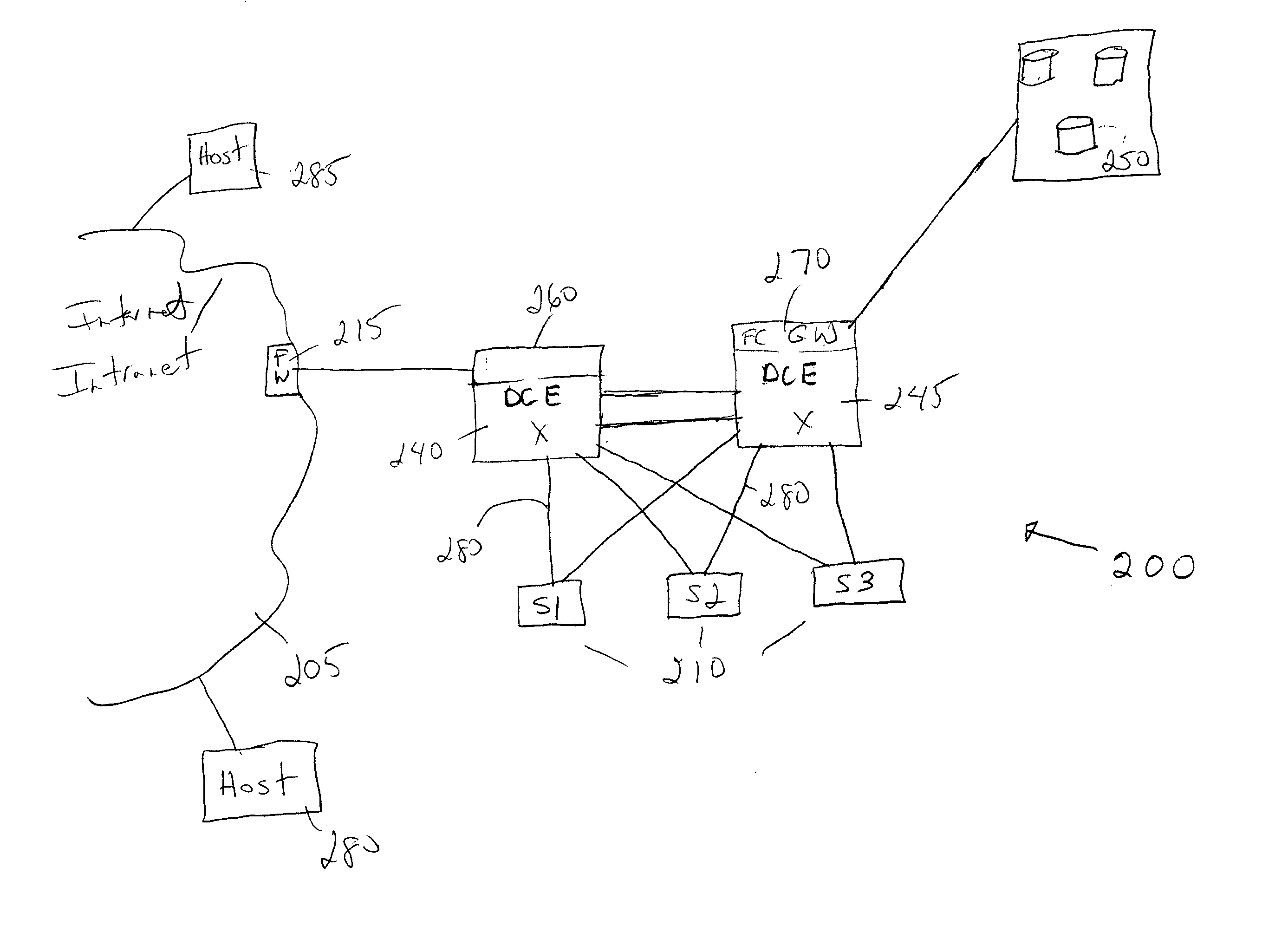
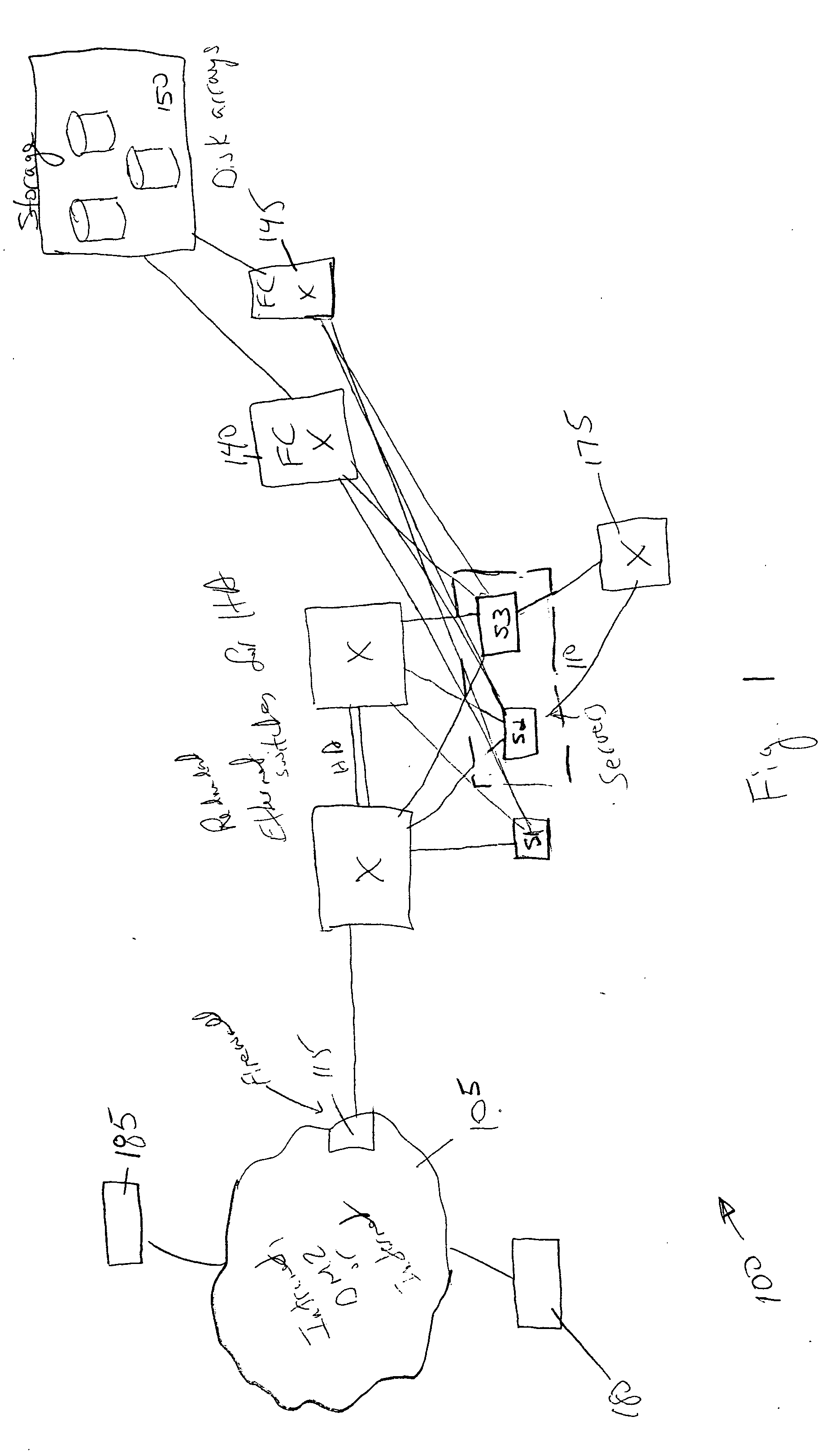
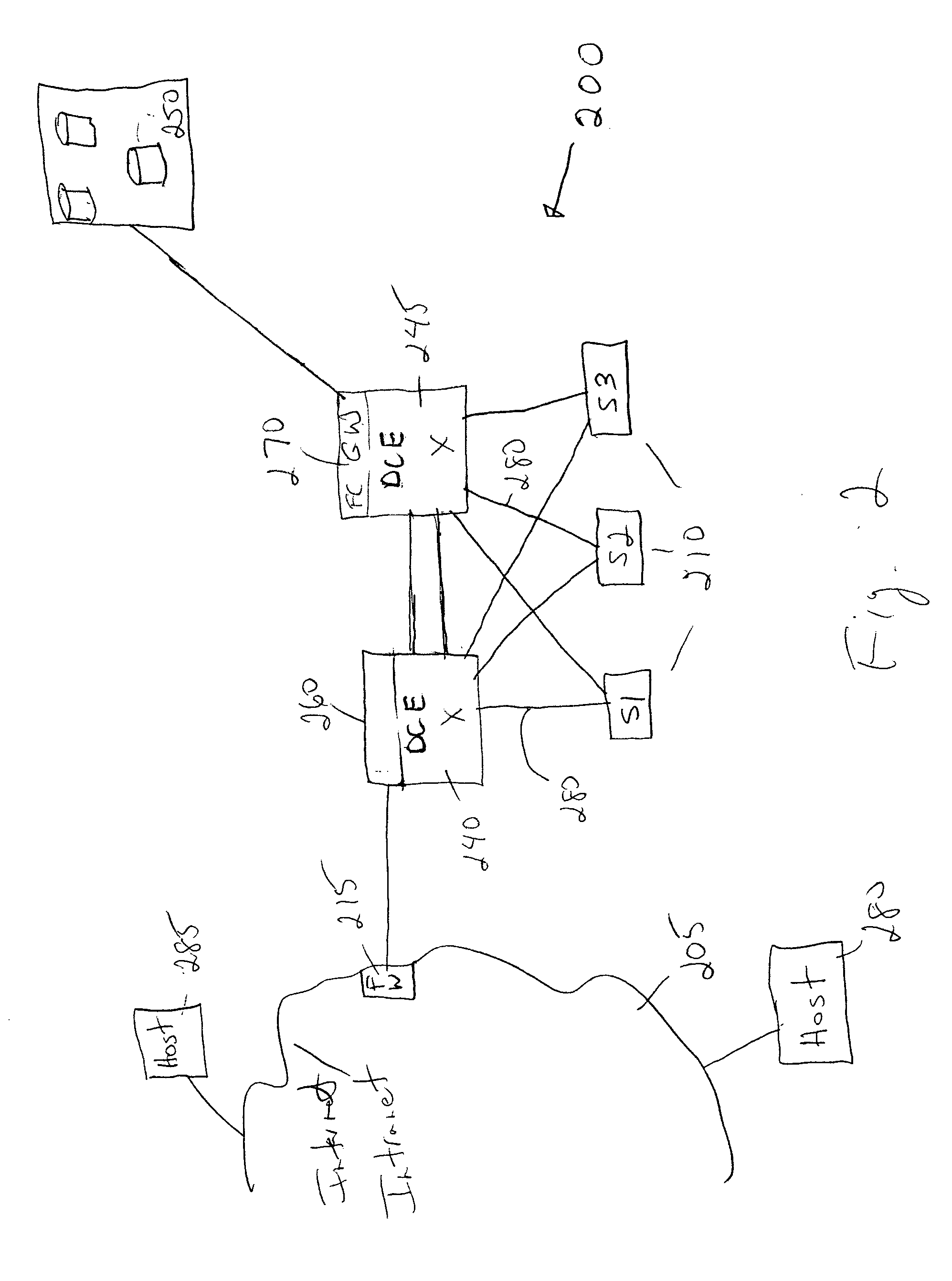
CROSS-REFERENCE TO RELATED APPLICATIONS [0001] This application claims priority to U.S. Provisional Application No. 60 / 621,396 (Attorney Docket No. CISCP404P), entitled “FC Over Ethernet” and filed on Oct. 22, 2004, which is hereby incorporated by reference in its entirety. This application is related to U.S. patent application Ser. No. ______ (Attorney Docket No. CISCP409), entitled “Fibre Channel Over Ethernet” and filed on Mar. 10, 2005, which is also hereby incorporated by reference in its entirety.BACKGROUND OF THE INVENTION [0002]FIG. 1 depicts a simplified version of a data center of the general type that an enterprise that requires high availability and network storage (e.g., a financial institution) might use. Data center 100 includes redundant Ethernet switches with redundant connections for high availability. Data center 100 is connected to clients via network 105 via a firewall 115. Network 105 may be, e.g., an enterprise Intranet, a DMZ and / or the Internet. Ethernet is ...

Claims


Application Information

Patent Timeline
IPC IPC(8): G06F15/173H04L47/32
CPCH04L12/4633H04L12/4641H04L47/10H04L47/13H04L47/24H04L47/266H04L47/32H04L47/39H04L69/22
Inventor GAI, SILVANOEDSALL, THOMASCAFIERO, LUCABERGAMASCO, DAVIDEDUTT, DINESHBONOMI, FLAVIO
Owner CISCO TECH INC
Learn More