Umbrella with improved hub

a hub and umbrella technology, applied in the field of umbrellas with improved hubs, can solve the problems of affecting the durability of use, and affecting the operation of users, so as to improve the durability and life, increase the durability and use ease, and reduce the stress of bearings

Inactive Publication Date: 2006-05-18
EDER FRED
View PDF24 Cites 13 Cited by
  • Summary
  • Abstract
  • Description
  • Claims
  • Application Information

AI Technical Summary

Benefits of technology

[0004] The present invention is an improved umbrella and umbrella hub. The inventive umbrella hub incorporates a spherically shaped ball joint knuckle secured to the inner end of the umbrella frame ribs and spreaders. The joint knuckles are received and retained in spherical bearing surfaces to provide pivoting movement of the ribs and spreaders. The joint knuckles have a radial dimension larger than the cross-sectional dimension of the rib or spreader to provide increased bearing area and consequent decreased bearing stresses. This geometry increases durability and life and ease of use. These advantages of the instant inventive design are particularly appreciated in larger umbrellas having a cover extended diameter in the range of six to twenty feet.

Problems solved by technology

Particularly, many umbrellas suffer from high weight which makes their manual operation difficult by the user.
High weight is a problem directly, and indirectly as producing friction between the relatively moving parts during erection of the umbrella canopy.
In addition, as devices often used outdoors in conditions introducing grit and moisture to the umbrella parts, umbrellas are susceptible to corrosion and wear which further hamper operation by users and produce a need for repair.
Prior art umbrellas do not provide sufficiently smooth operation for manual operation by single person users, particularly in larger umbrellas.
While the wires provide an axis of rotation for the moving ribs and spreaders, the rotational friction is inherently high in such a design.
In addition, due to the small bearing area between the wire and the rib or spreader hole, high bearing forces produce a high level of wear and deterioration of the parts, increasing the problem.
In any umbrella design where the bearing area is small at the point of rotation of the ribs and spreaders, bearing and friction forces will likely be a source of problems for the user.
In addition, the design of prior art umbrellas do not provide for easy disassembly for maintenance or replacement of parts.

Method used


Image

  • Umbrella with improved hub
  • Umbrella with improved hub
  • Umbrella with improved hub

Examples


Embodiment Construction

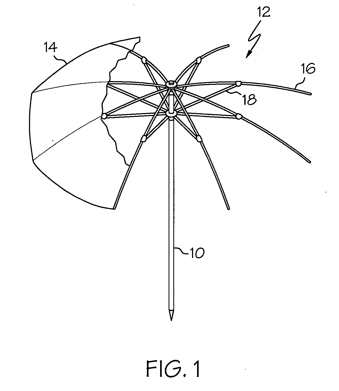
[0011]FIG. 1 is a perspective view of an umbrella according to the invention. The umbrella includes a center ridge pole 10 which is the main support and which may be, as in the prior art, pointed at its lower end for penetration into the ground. At the top of the ridge pole 10 is attached a collapsible framework 12 which supports a flexible cover 14 (shown partially cut away). The cover 14 may be formed of fabric, plastic, rubber-coated fabric, or similar materials known in the art for providing rain or sun protection. The general construction, cooperation, and operation of the framework 12 and the cover 14 are known in the art. While the embodiment shown in the figure has a framework 12 and cover 14 of overall generally circular geometry, other geometries such as square are also contemplated.

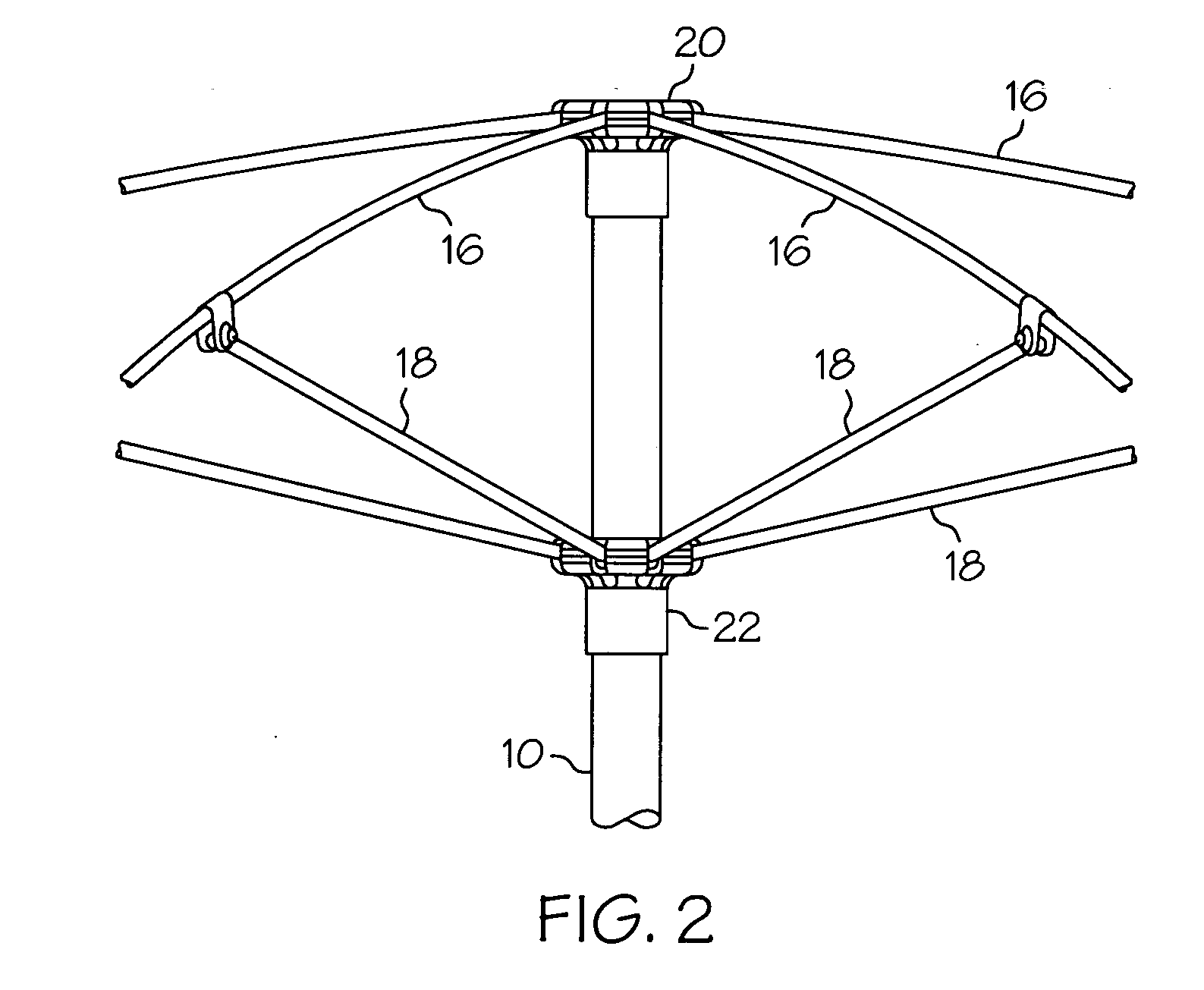
[0012] The framework 12 consists of, essentially, elongated and somewhat flexible ribs 16 and supporting spreaders 18. The ribs 16 are under, and attached to, the cover 14, and when fully expa...


PUM


Abstract

An improved umbrella includes a durable hub including a number of spherical rotating joint knuckles captured in a hub body. The joint knuckles provide rotational movement of rib and spreader elements which support a flexible umbrella cover. The joint knuckles provide increased bearing surface area that increases ease of use and durability. The hub design enables identical hub bodies to be used for a spreader hub and a rib hub.

Description

BACKGROUND OF THE INVENTION [0001] The present invention pertains to collapsible umbrellas for personal use as are typically used for protection from the sun. In particular, the present invention is an umbrella including an improved hub design providing easy and durable operation for umbrellas of the larger sizes and weights. [0002] Such umbrellas are generally known in the prior art. U.S. Pat. No. 5,193,566 to Chen; U.S. Pat. No. 5,247,956 to Vincent; U.S. Pat. No. 6,076,540 to You; U.S. Pat. No. 6,314,976 to Clarke; and U.S. Pat. No. 6,298,867 to Chang disclose various designs which attempt to resolve some of the weaknesses of the collapsible umbrella concept. Particularly, many umbrellas suffer from high weight which makes their manual operation difficult by the user. High weight is a problem directly, and indirectly as producing friction between the relatively moving parts during erection of the umbrella canopy. In addition, as devices often used outdoors in conditions introduci...

Claims


Application Information

Patent Timeline
Patent Type & Authority Applications(United States)
IPC IPC(8): A45B25/00
CPCA45B25/06Y10T403/341Y10T403/443A45B25/10
Inventor EDER, FRED
Owner EDER FRED
Why Eureka
Try Eureka