Cracking tube having helical fins

a technology of helical fins and cracking tubes, which is applied in the direction of indirect heat exchangers, furnaces, lighting and heating apparatus, etc., can solve the problems of reducing the coefficient of heat transfer, reducing the fraction of hydrocarbons produced in excess, and reducing the pressure loss of fluids, so as to achieve the effect of high efficiency and minimal fluid pressure loss

Inactive Publication Date: 2006-05-18
KUBOTA LTD
View PDF1 Cites 28 Cited by
  • Summary
  • Abstract
  • Description
  • Claims
  • Application Information

AI Technical Summary

Benefits of technology

[0013] The tube of this construction is adapted to minimize the pressure loss of the fluid inside the tube while permitting the helical fins to transfer heat to the inside fluid with a high efficiency.

Problems solved by technology

If the gas is heated at a high temperature over a prolonged period of time, lighter fractions of hydrocarbons (methane, free carbons, etc.) will be produced in excessive amounts or the product of cracking will undergo, for example, a polycondensation reaction to reduce the yield of the desired product.
Promoted coking (deposition of free carbon on the tube inner wall) will also result to lower the coefficient of heat transfer, giving rise to a need to perform decoking frequently.
These examples have a great effect to stir the fluid within the tubes and are highly efficient in heat transfer to the fluid within the tubes, whereas the internal pressure of the fluid inside the tubes builds up owing to a great pressure loss of the fluid, entailing the drawback that the cracking operation produces ethylene, propylene or the like in a lower yield.
However, the fins positioned in parallel to the tube axis fail to produce a sufficient effect to stir the fluid inside the tubes and to achieve the desired heat transfer performance.

Method used


Image

  • Cracking tube having helical fins
  • Cracking tube having helical fins
  • Cracking tube having helical fins

Examples


example 1

[0051] Test Tubes T1 to T5 were prepared and checked for film heat transfer coefficient h (W / m2 / K) and pressure loss dP (Pa).

[0052] T1 is according to the invention, and T2 to T5 are comparative examples. Table 1 shows the particulars about these test tubes.

TABLE 1Test TubesFin SpecificationsCircum-CircularNumberferentialarcNumberof rowsAnglelengthlengthNumberperin circum-ofLengthof innerDraw-Thick-as pro-ofturn offerentialincli-ratioNo.I.D.surfaceingShapeHeightnessjectedhelixeshelixdirectionnationPitchR *NoteT142 mm132 mmFIG.Dis-2.2 mm8 mm16.5 mm14—60 deg76 mm0.5Inven-1crete,tionhelicalT242 mm132 mmFIG.Con-2.2 mm8 mm18.9 mm1——60 deg76 mm1.0Comp.12tinuous,ex.helicalT342 mm132 mmFIG.Dis-2.2 mm8 mm18.9 mm14 and 3—60 deg76 mm1.0Comp.13crete,alter-ex.helicalnating(stag-gered)T442 mm132 mmFIG.Paral-2.2 mm8 mm18.9 mm——8——0.5Comp.14lel to**ex.tubeaxisT542 mm132 mmNoneNo fin—————————Comp.ex.

(Note)

* Circular arc length ratio R = (sum of circular arc lengths of fins along every turn of he...

example 2

[0064] Next, a thermal fluid analysis was conducted using a W-shaped coil shown in FIG. 11 and simulating the conditions under which reactors are used for producing ethylene to determine pressure loss of the fluid inside the coil and yields of ethylene and propylene.

[0065] The coil shown in FIG. 11 includes tubes (straight tubular portions) which are 63.5 mm in inside diameter, 6.4 mm in wall thickness and 9.6 m in length and which provide a first pass, second pass, third pass and fourth pass, respectively, as arranged in this order from the upstream side downstream. Table 2 shows the construction of Test Tubes T6 to T9.

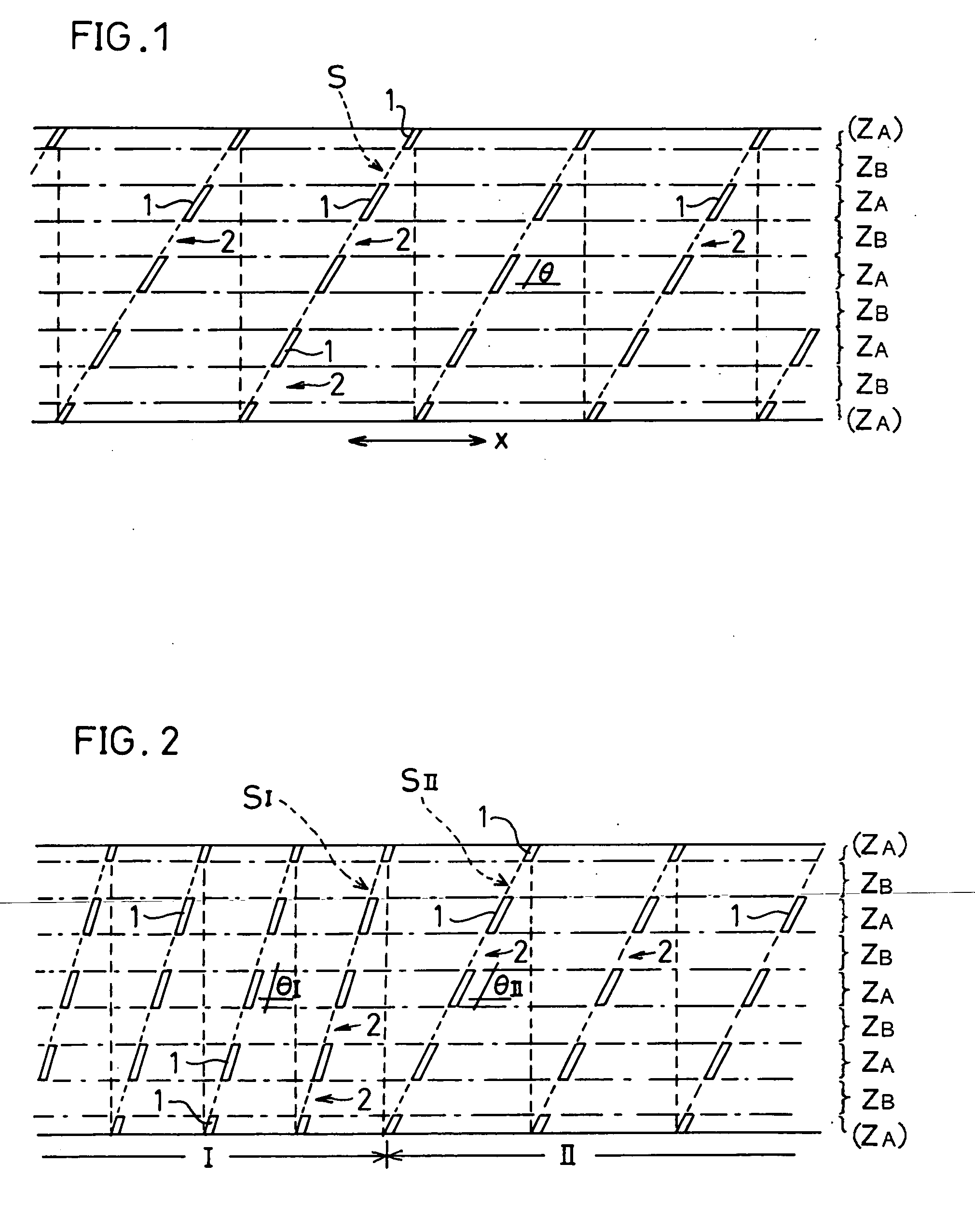
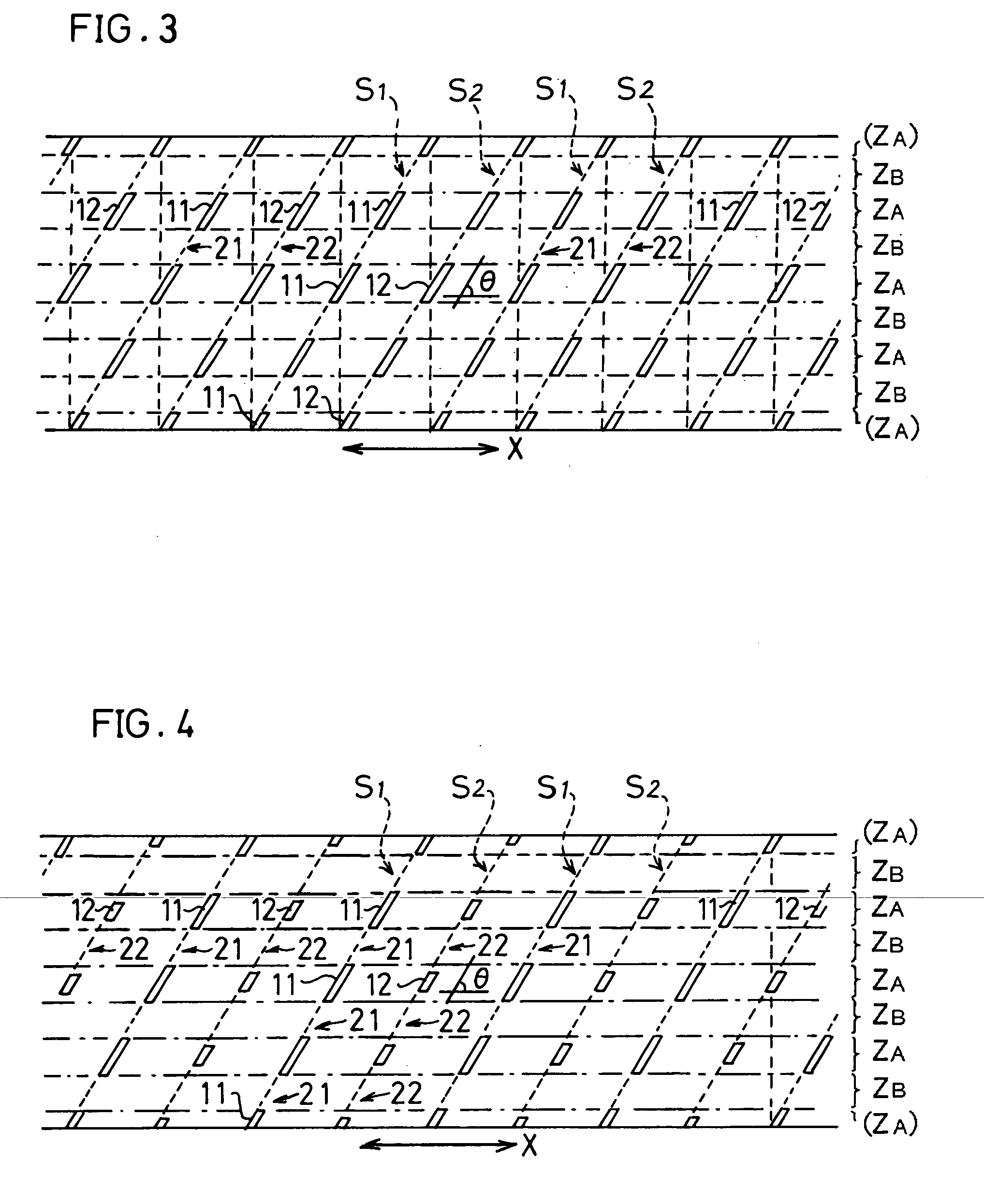
[0066] Test Tube T6 is according to the invention, and Test Tubes T7 to T9 are comparative examples. As to the arrangement of fins on the tube (straight tubular portion), Test Tube T6 is the same as is shown in FIG. 1, T7 as is shown in FIG. 13, and T8 as is shown in FIG. 12. T9 is an example which has no fins.

TABLE 2Test TubesStructure ofT 6T 7T 8T 9passes(Inven...


PUM

PropertyMeasurementUnit
angle of inclinationaaaaaaaaaa
diameteraaaaaaaaaa
diameteraaaaaaaaaa

Abstract

A cracking tube (50) for use in thermal cracking furnaces for producing ethylene or the like has fins (1) formed on an inner surface thereof and inclined with respect to an axis of the tube for stirring a fluid inside the tube. The fins are arranged discretely on one or a plurality of helical loci, and the tube inner surface has regions (ZB) wherein no fins are present over the entire axial length of the tube from one axial end of the tube to the other axial end thereof.

Description

TECHNICAL FIELD [0001] The present invention relates to cracking tubes for use in thermal cracking reactors for producing ethylene or the like, and more particularly to a cracking tube which is provided on the inner surface thereof with fins for stirring the fluid therein and which is adapted to suppress pressure losses to the greatest possible extent while effectively promoting heat transfer to the fluid therein. BACKGROUND ART [0002] Olefins such as ethylene, propylene or the like are produced by thermally cracking material gases of hydrocarbons (naphtha, natural gas, ethane, etc.). The thermal cracking reaction is conducted by introducing the hydrocarbon material gas and steam into a cracking coil disposed within a heating furnace supplied with heat from outside, and heating the mixture to a reaction temperature range while the mixture flows through the coil at a high velocity. [0003] Typically, the cracking coil comprises a plurality of (straight) tubes which are connected into ...

Claims


Application Information

Patent Timeline
Patent Type & Authority Applications(United States)
IPC IPC(8): F28F13/18F28F13/00F28F1/20F28F1/30F28F1/36B01F5/00B01F5/06B01J19/24C10G9/20F27D27/00F28F1/40
CPCB01F2005/0626B01F2005/0636B01J19/006F28F1/40C10G9/20F28D2021/0022B01J19/2415B01F25/43162B01F25/431971
Inventor INUI, MASAHIROHAMADA, KAORUOTSUBO, KENJI
Owner KUBOTA LTD
Why Eureka
Try Eureka