Parallel flow evaporator with spiral inlet manifold
- Summary
- Abstract
- Description
- Claims
- Application Information
AI Technical Summary
Benefits of technology
Problems solved by technology
Method used
Image
Examples
Embodiment Construction
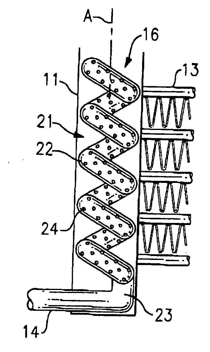
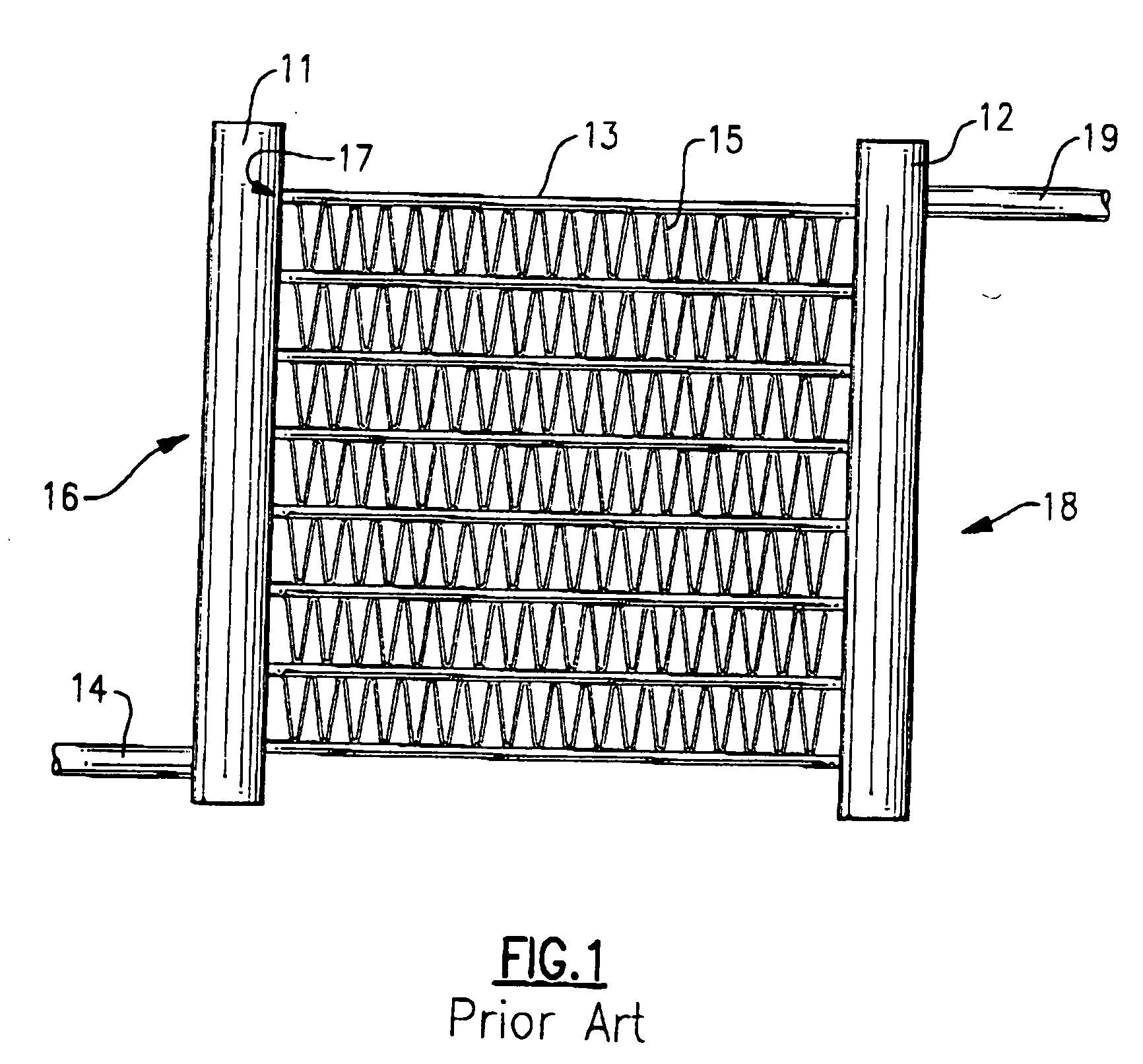
[0023] Referring now to FIG. 1, a parallel flow heat exchanger is shown to include an inlet header or manifold 11, an outlet header or manifold 12 and a plurality of parallel disposed channels 13 fluidly interconnecting the inlet manifold 11 to the outlet manifold 12. Generally, the inlet and outlet headers 11 and 12 are cylindrical in shape, and the channels 13 are tubes (or extrusions) of flattened or round shape. Channels 13 normally have a plurality of internal and external heat transfer enhancement elements, such as fins. For instance, external fins 15, disposed therebetween for the enhancement of the heat exchange process and structural rigidity are typically furnace-brazed. Channels 13 may have internal heat transfer enhancements and structural elements as well.
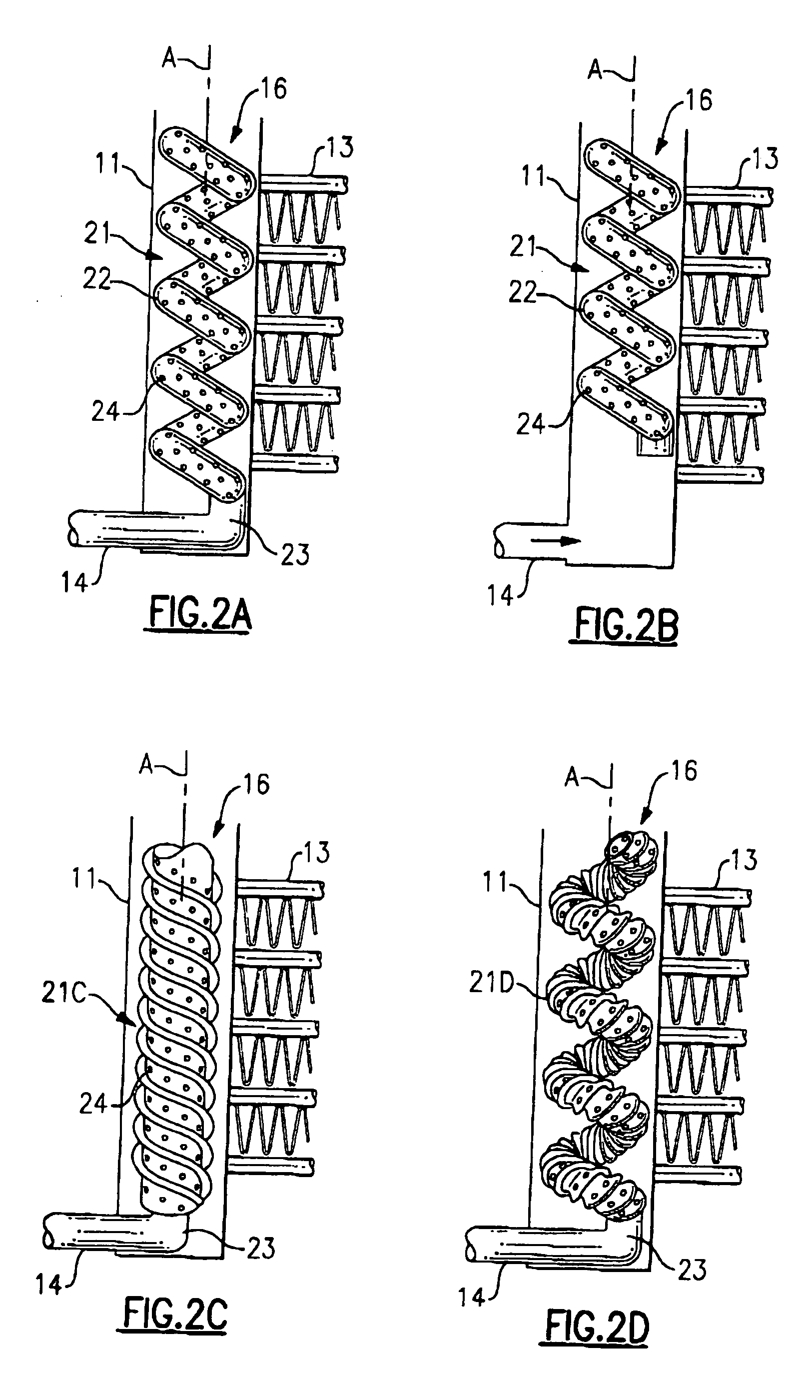
[0024] In operation, two-phase refrigerant flows into the inlet opening 14 and into the internal cavity 16 of the inlet header 11. From the internal cavity 16, the refrigerant, typically in the form of a mixture of li...
PUM
| Property | Measurement | Unit |
|---|---|---|
| Length | aaaaa | aaaaa |
| Flow rate | aaaaa | aaaaa |
| Diameter | aaaaa | aaaaa |
Abstract
Description
Claims
Application Information
 - R&D
- Intellectual Property
- Life Sciences
- Materials
- Tech Scout
- Unparalleled Data Quality
- Higher Quality Content
- 60% Fewer Hallucinations
Browse by: Latest US Patents, China's latest patents, Technical Efficacy Thesaurus, Application Domain, Technology Topic, Popular Technical Reports.
© 2025 PatSnap. All rights reserved.Legal|Privacy policy|Modern Slavery Act Transparency Statement|Sitemap|About US| Contact US: help@patsnap.com


