Polyolefin microporous membrane

a polyolefin microporous membrane and polyolefin technology, applied in the direction of membranes, cell components, electric/magnetic/electromagnetic heating, etc., can solve the problems of reduced membrane strength, separation of electrodes may be injured, uneven surface of electrodes, etc., to achieve high permeability without decreasing membrane strength and high surface porous structure. uniform

Inactive Publication Date: 2006-05-18
ASAHI KASEI CHEM CORP
View PDF3 Cites 56 Cited by
  • Summary
  • Abstract
  • Description
  • Claims
  • Application Information

AI Technical Summary

Benefits of technology

[0012] The present invention is intended to provide a microporous membrane that can retain a high permeability without decreasing in the membrane strength and has a highly uniform surface porous structure free from local nonuniformity of the permeability.

Problems solved by technology

Moreover, the surfaces of the electrodes are not always smooth and there is a fear that the separator may be injured because active material particles of various sizes become protruded or a stress is concentrated at the contact portion with an electrode tab.
However, the attainment of high ion permeability by resort to the prior art has been disadvantageous in that the membrane strength is decreased by an excessive increase in the porosity, and that the surface porous structure becomes nonuniform, so that the permeability becomes locally nonuniform, resulting in a decreased battery capacity in initial charge and discharge.
In a microporous membrane for the separator, how to impart such various characteristics to the microporous membrane while maintaining a good balance among them, is an important technical issue.
The veiny-structure characteristic of said microporous membrane tends to be observed in a microporous membrane obtained by conducting only stretching after extraction (hereinafter referred to as post-extraction stretching), and the veiny structure is disadvantageous in that it becomes a nonuniform surface-porous structure, resulting in a nonuniform permeability.
Moreover, the microporous membrane having said veiny structure is disadvantageous also in having a low membrane strength because a three-dimensional network comprising efficiently oriented micro-fibrils cannot be formed in said microporous membrane.
The dense structure characteristic of this microporous membrane tends to be observed in a microporous membrane obtained by conducting only stretching before extraction (hereinafter referred to as pre-extraction stretching), and the dense structure is disadvantageous in that it is poor in permeability because the spaces among the micro-fibrils are too narrow.
Thus, the membrane cannot have both a high membrane strength and a high permeability.
This microporous membrane, however, is disadvantageous in that a veiny structure comprising a large number of thick macro-fibrils, is observed in the surface structure of the microporous membrane, resulting in a nonuniform permeability, as in the case of the microporous membranes obtained by processes similar to that for said microporous membrane which are described in Comparative Examples 3 and 4 given hereinafter.
Said microporous membrane is disadvantageous also in having a low membrane strength.
Such a slit-like pore structure characteristic of this microporous membrane tends to be observed in a microporous membrane produced by a so-called lamella-stretching hole-making method, and cannot give an effective permeability in proportion to the pore volume because of the slender shape of the pores.
Furthermore, because of the presence of the thick macro-fibrils in a large number, the surface porous structure is not uniform, resulting in a nonuniform permeability.
The microporous membrane disclosed in the above reference also involves a problem of low membrane strength.

Method used


Image

  • Polyolefin microporous membrane
  • Polyolefin microporous membrane
  • Polyolefin microporous membrane

Examples


reference example 1

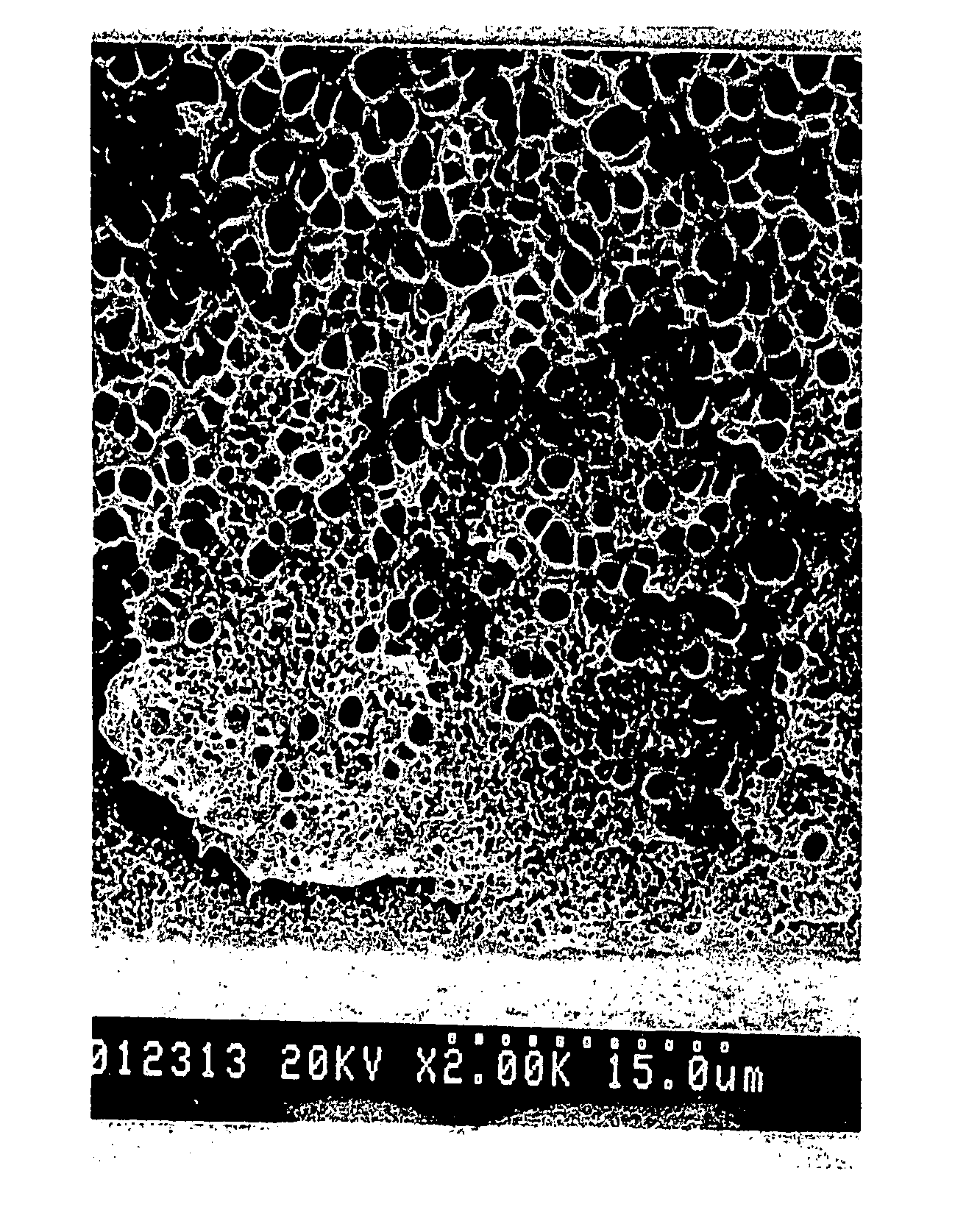
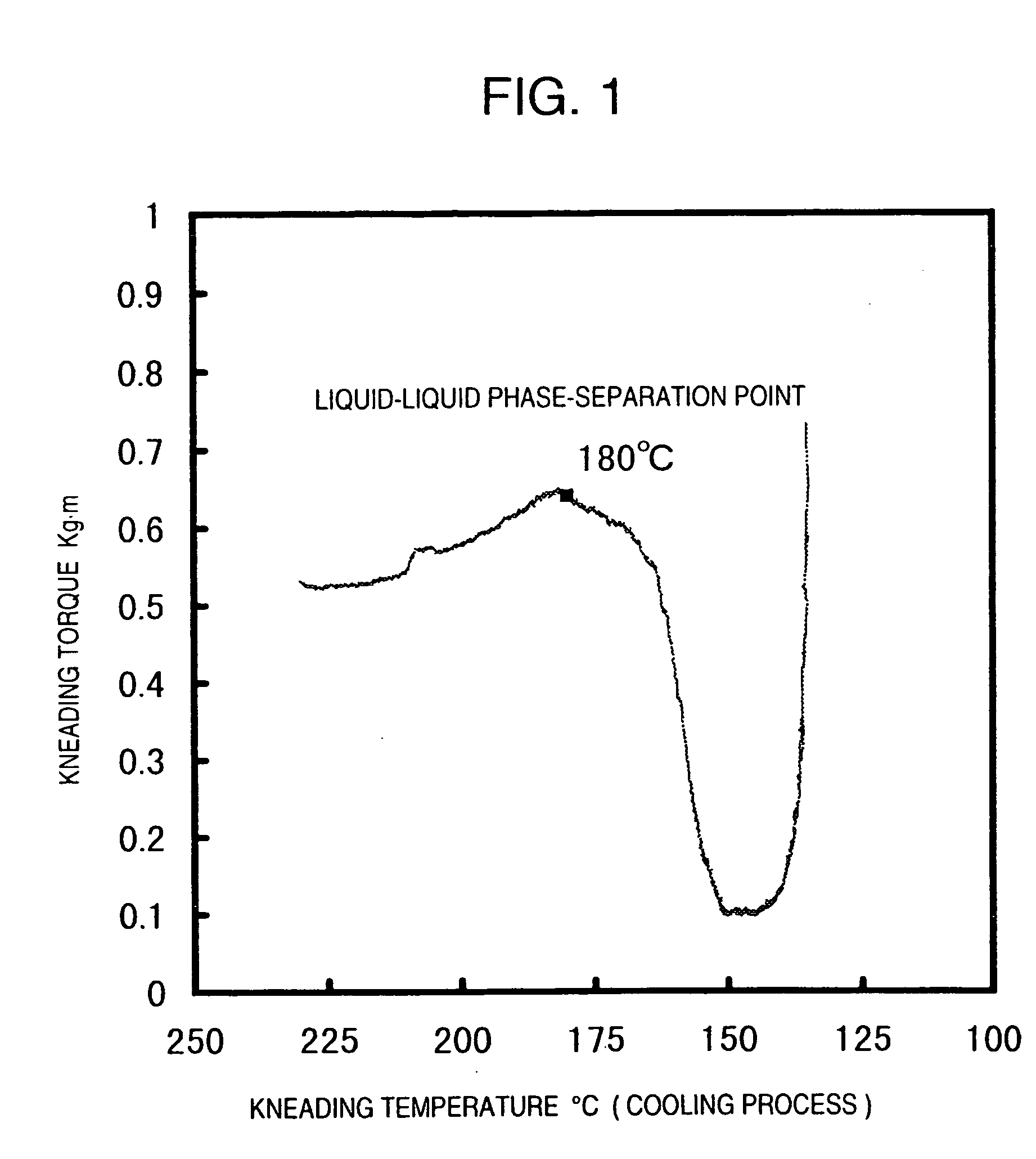
[0122] 40 Parts by weight of a high-density polyethylene (weight average molecular weight 250,000, molecular weight distribution 7, density 0.956), 0.5 part by weight of 2,6-di-t-butyl-p-cresol and 60 parts by weight of di(2-ethylhexyl) phthalate were mixed and then fed into Laboplastomill. They were melt-kneaded for 5 minutes at a kneading temperature of 230° C. and at a screw revolution of 50 rpm, and the stabilization of the resin temperature and the kneading torque were awaited. Then, the change of the kneading torque with a lowered temperature was observed by setting the screw revolution at 10 rpm and air-cooling the kneaded composition from the original temperature of 230° C. by switching off a heater, while continuing the screw kneading, thereby evaluating a phase separation mechanism. From the characteristic graph shown in FIG. 1, it was found that said composition had a thermally induced liquid-liquid phase separation point of 180° C.

reference example 2

[0123] A phase separation mechanism was evaluated by the same method as described in Reference Example 1, except for using 45 parts by weight of the same high-density polyethylene as described in Reference Example 1 and 55 parts by weight of di(2-ethylhexyl) phthalate. It was found that the resulting composition had a thermally induced liquid-liquid phase separation point of 168° C.

reference example 3

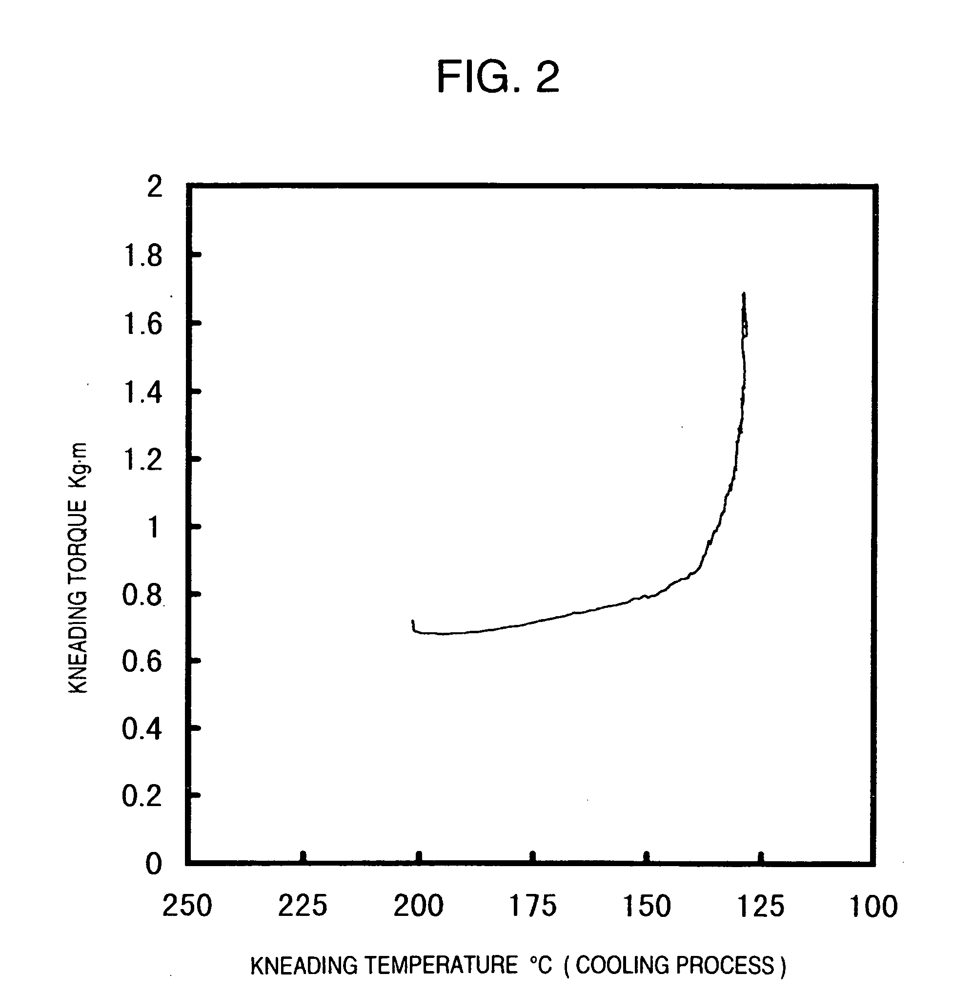
[0124] A phase separation mechanism was evaluated by the same method as described in Reference Example 1, except for using liquid paraffin (kinematic viscosity at 37.8° C.: 75.9 cSt) as a solvent and setting the kneading temperature and the original temperature at 200° C. From the characteristic graph shown in FIG. 2, it was found that the resulting composition had no thermally induced liquid-liquid phase separation point.


PUM

PropertyMeasurementUnit
diameteraaaaaaaaaa
diameteraaaaaaaaaa
thicknessaaaaaaaaaa

Abstract

The present invention provides a polyolefin microporous membrane having a surface structure comprising fine spaces formed by partitioning micro-fibrils and a network formed by uniform dispersion of said micro-fibrils, wherein the average diameter of the micro-fibrils is 20 to 100 nm and the average distance between the micro-fibrils is 40 to 400 nm; and a process for producing said poly-olefin microporous membrane.

Description

TECHNICAL FIELD [0001] The present invention relates to a polyolefin microporous membrane suitable as a battery separator used in various cylindrical batteries, rectangular batteries, thin batteries, button-shaped batteries, electrolytic capacitors, etc., and to a process for producing a polyolefin microporous membrane. BACKGROUND ART [0002] Microporous membranes have been used as materials for filter media for water purifiers and the like, various separation membranes, air-permeable clothing, separators for batteries, and electrolytic capacitors, etc. In recent years, there is a growing demand for microporous membranes for use in secondary lithium-ion batteries, and separators for the batteries have become required to have high performance characteristics, with an increased energy density of the batteries. [0003] Since an electrolytic solution and chemicals, such as positive- and negative-electrode active materials, are used in the secondary lithium-ion batteries, polyolefin type p...

Claims


Application Information

Patent Timeline
Patent Type & Authority Applications(United States)
IPC IPC(8): B29C55/00H05B6/00B01D67/00B01D69/02B01D71/26H01M50/417H01M50/489H01M50/491
CPCB01D67/0027B01D67/003B01D69/02B01D71/26H01M2/162B01D2323/20Y02E60/10H01M50/44H01M50/417H01M50/491H01M50/489
Inventor HOSHUYAMA, IZUMIKONDO, TAKAHIKO
Owner ASAHI KASEI CHEM CORP
Why Eureka
Try Eureka