Power supply apparatus for fuel injection apparatus

a technology of power supply apparatus and fuel injection, which is applied in the direction of engine starters, electric generator control, electric control, etc., can solve the problems of increasing the number of windings of the armature coil, reducing the power generation output during a high-speed rotation of the engine, and requiring an expensive comparator, so as to reduce the cost of the generator, simplify the connection work, and reduce the cost

Active Publication Date: 2006-05-18
MAHLE INT GMBH
View PDF9 Cites 5 Cited by
  • Summary
  • Abstract
  • Description
  • Claims
  • Application Information

AI Technical Summary

Benefits of technology

[0018] Providing the above described voltage adjusting signal supply circuit makes it possible to turn ON, when the output voltage of the power supply apparatus increases excessively, the MOSFET to short-circuit the output of the generator and reduce the output voltage of the power supply apparatus, and cancel, when the output voltage of the power supply apparatus falls below a set value, the short-circuit of the output of the generator, to increase the output voltage, and thereby keep the output voltage of the power supply apparatus to close to the set value and prevent an excessive voltage from being given to the load.
[0019] As described above, according to the present invention, since a control voltage supply circuit is provided with a control voltage supply control switch which is ON / OFF-controlled by the drain-source voltage of each MOSFET so as to be set in an OFF-state when a forward voltage is applied to the parasitic diode of each MOSFET and set in an ON-state when a reverse voltage is applied to the parasitic diode of each MOSFET, which gives a control voltage equal to or higher than the ON-level between the gate and source of each MOSFET for a period during which the control voltage supply control switch is in an OFF-state, it is possible to give each MOSFET a drive signal for ON / OFF-control according to the polarity of the drain-source voltage of each MOSFET and a control voltage for reducing channel loss without comparing the potentials of the input terminals. Therefore, it is possible to omit a comparator which compares a potential of each input terminal with potentials of other input terminals and thereby reduce the cost.
[0020] Furthermore, in the present invention, a control voltage is generated by controlling the control voltage supply control switch according to the polarity of the drain-source voltage of each MOSFET, and therefore it is not necessary to distinguish between phases when connecting output leads of the generator to the input terminals of the power supply apparatus. Therefore, it is not necessary to change the colors of the output leads of the generator one another and it is thereby possible to reduce the cost of the generator. Furthermore, when connecting the output leads of the generator to the input terminals, it is not necessary to distinguish colors of the output leads, which can simplify the connection work.

Problems solved by technology

For this purpose, the number of windings of an armature coil of the magneto-generator may be increased, but increasing the number of windings of the armature coil reduces power generation output during a high-speed rotation of the engine.
Decreasing the number of windings of the armature coil to improve power generation output during a high-speed rotation of the engine increases the rotational speed at which the fuel injection apparatus can operate normally, which deteriorates the starting characteristic of the engine.
As described above, the conventional power supply apparatus is provided with a comparator which compares a potential of each input terminal of each phase with a potential of other input terminal of other phase to detect the polarity of the voltage applied between the drain and source of each MOSFET, and thereby requires an expensive comparator and cannot help but increase the cost.
For example, colors of output leads of the generator must be changed to identify phases of the output leads, which cause the cost of the generator to be increased.

Method used


Image

  • Power supply apparatus for fuel injection apparatus
  • Power supply apparatus for fuel injection apparatus
  • Power supply apparatus for fuel injection apparatus

Examples


Embodiment Construction

[0026] With reference now to the attached drawings, embodiments of the present invention will be explained below.

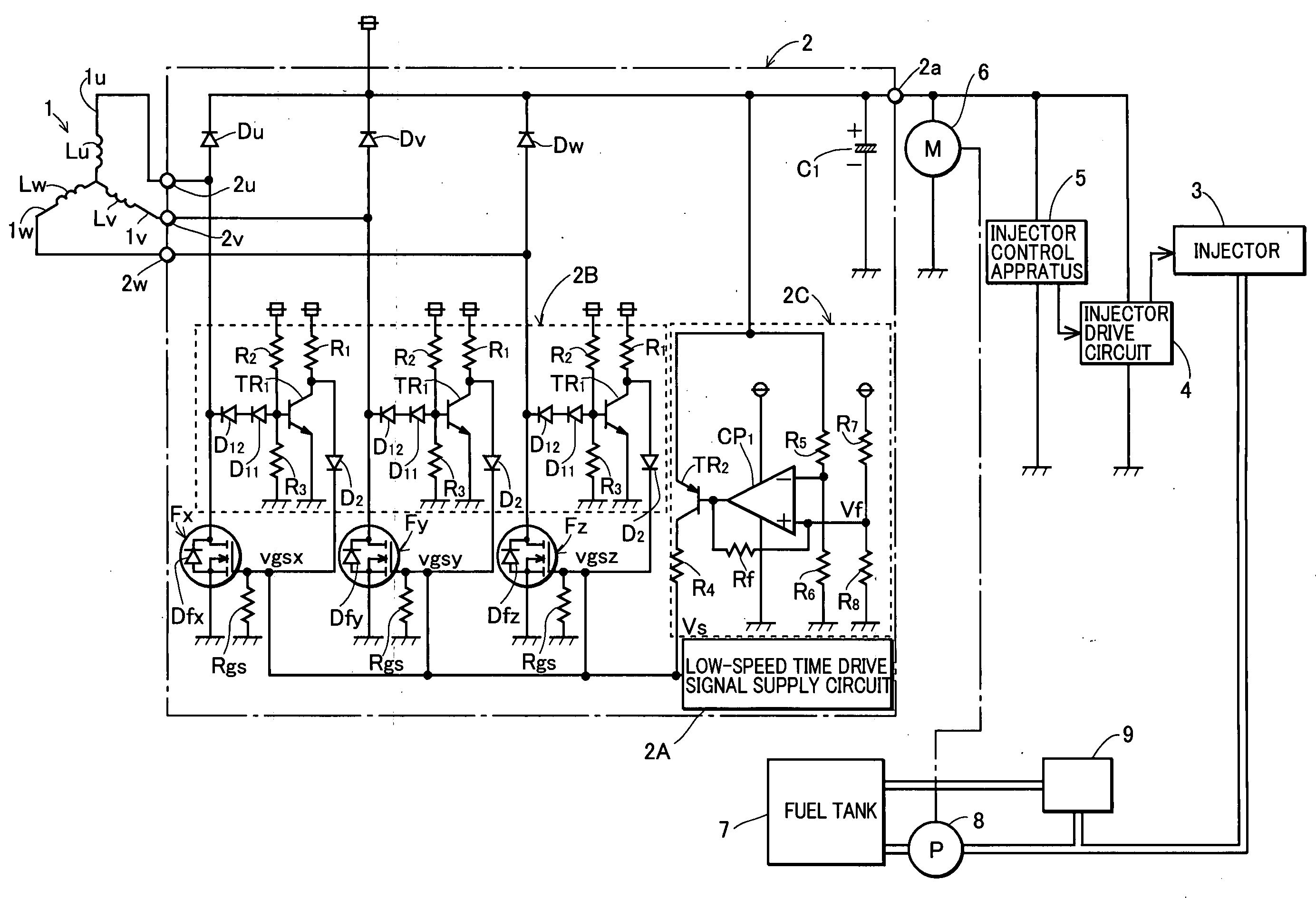
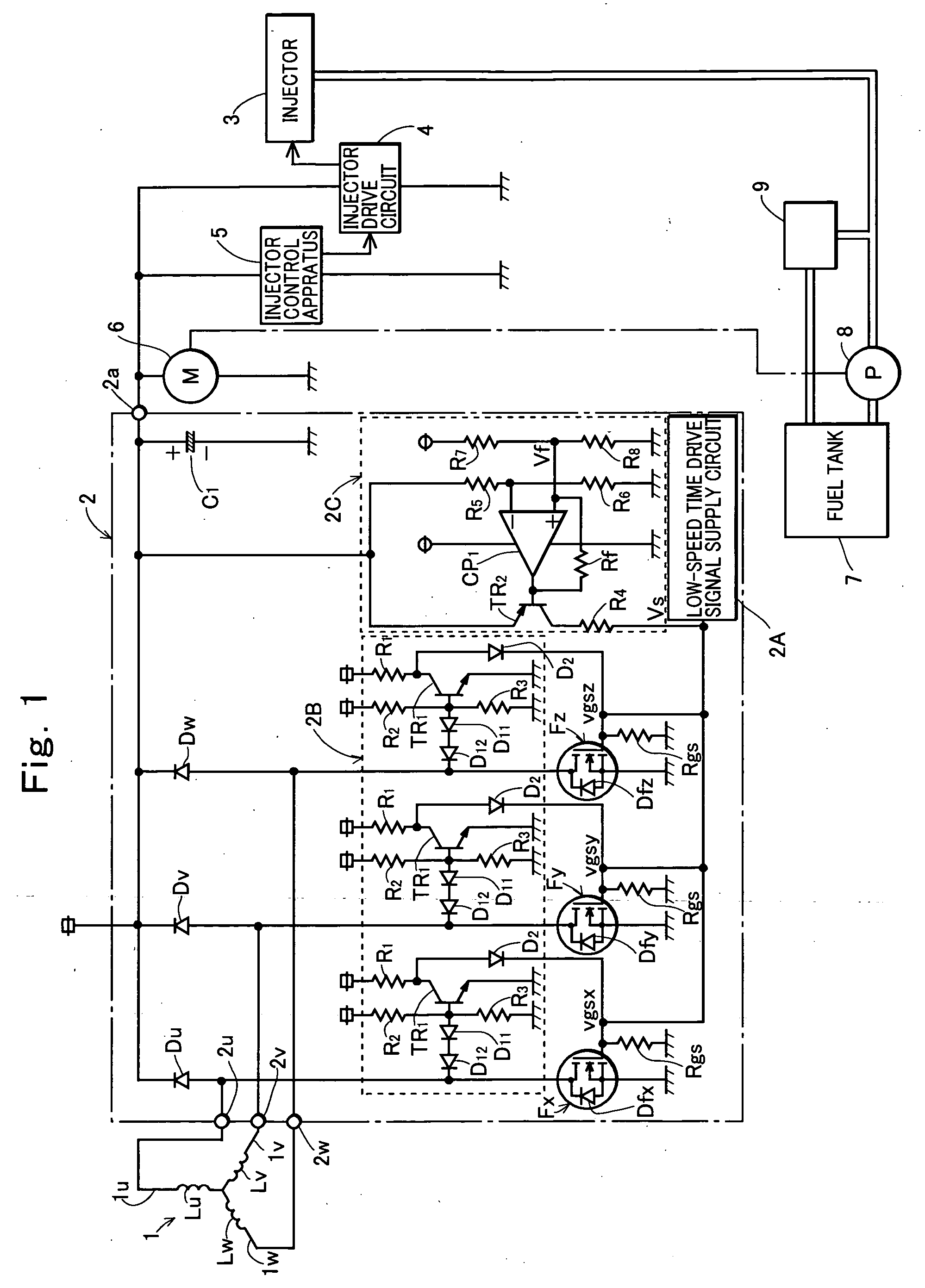
[0027]FIG. 1 shows a first embodiment of a power supply apparatus according to the present invention. The present invention is applied to a power supply apparatus for a fuel injection apparatus comprised of n (n: integer of 2 or greater) input terminals to which a single-phase or multi-phase AC voltage is input from a magneto AC generator driven by an internal combustion engine, m (m: integer of 2 or greater and not greater than n) MOSFETs with ones of drains and sources commonly connected and the others connected to m input terminals of the n input terminals and parasitic diodes formed between the drains and sources of the m MOSFETs and 2n-m rectification diodes provided so as to constitute together a diode bridge full-wave rectifier circuit which rectifies an AC voltage given to the n input terminals, where m=n=3 is assumed in the embodiment shown in FIG. 1.

[0028] In ...


PUM


Abstract

A power supply apparatus comprised of a bridge circuit made up of rectification diodes and MOSFETs for rectifying an output of a generator through a full-wave rectifier circuit comprised of rectification diodes and parasitic diodes of the MOSFETs and obtaining a supply voltage of a fuel injection apparatus, the power supply apparatus being comprised of an FET control section which turns ON/OFF the MOSFETs to step up the output voltage of the generator and a transistor provided for each MOSFET, which is set in an ON-state for a period during which a reverse voltage is applied to a parasitic diode of each MOSFET and set in an OFF-state for a period during which a forward voltage is applied to the parasitic diode of each MOSFET, wherein a control voltage for turning ON the MOSFET is given between the gate and source of the corresponding MOSFET for a period during which each transistor is in an OFF-state.

Description

TECHNICAL FIELD OF THE INVENTION [0001] The present invention relates to a power supply apparatus for a fuel injection apparatus which supplies a supply voltage to the fuel injection apparatus of an internal combustion engine. BACKGROUND OF THE INVENTION [0002] A fuel injection apparatus for supplying fuel to an internal combustion engine which drives a vehicle without mounting no battery is driven by a power supply apparatus which generates a DC voltage using a magneto AC generator driven by the internal combustion engine as a power supply. When a fuel injection apparatus is operated using a magneto-generator driven by the internal combustion engine as a power supply, it is necessary to output a sufficiently high voltage from the power supply apparatus during low-speed rotation of the engine in order to improve a starting characteristic of the internal combustion engine. For this purpose, the number of windings of an armature coil of the magneto-generator may be increased, but incr...

Claims


Application Information

Patent Timeline
Patent Type & Authority Applications(United States)
IPC IPC(8): H02J1/00
CPCB60R16/03F02D41/20F02D2041/2072H02M7/217H02M1/0085
Inventor UEMURA, KIYOSHI
Owner MAHLE INT GMBH
Why Eureka
Try Eureka