Testing system for solar cells

a solar cell and test system technology, applied in photovoltaics, power supply testing, electronic circuit testing, etc., can solve the problems affecting the quality of solar cells supplied or already tested, and requiring a relatively large amount of space. , to achieve the effect of reducing the cycle time of solar cell testing

Inactive Publication Date: 2006-05-18
MANZ AUTOMATION
View PDF15 Cites 83 Cited by
  • Summary
  • Abstract
  • Description
  • Claims
  • Application Information

AI Technical Summary

Benefits of technology

[0022] A refinement of this embodiment in which successive belt segments are spaced apart from one another three-dimensionally in the conveying direction by less than the length of one solar cell is also advantageous. In this way, no separate devices are necessary for transferring the solar cells to be conveyed from one belt to the next.
[0023] While in testing systems of the prior art, until now area scanning cameras were used for the optical checking, which survey the surface of the applicable solar cell in stopped times in one cycle, in a preferred embodiment of the testing system of the invention it is provided that the optical checking device includes at least one line scanning camera, which preferably scans the solar cells, moving past it on the conveyor belt system, from above. In this way, the optical checking can be done even continuously, ...

Problems solved by technology

However, besides this relatively slow cycle time, the known testing systems also have still other disadvantages:
Because of the use of robot arms and indexing turntables, such devices are relatively expensive and require a relatively large amount of space.
When the solar cells to be tested are shifted from the first conveyor device to the second conveyor device and after the conclusion of the checking are shifted from the second conveyor devi...

Method used


Image

  • Testing system for solar cells
  • Testing system for solar cells
  • Testing system for solar cells

Examples


Embodiment Construction

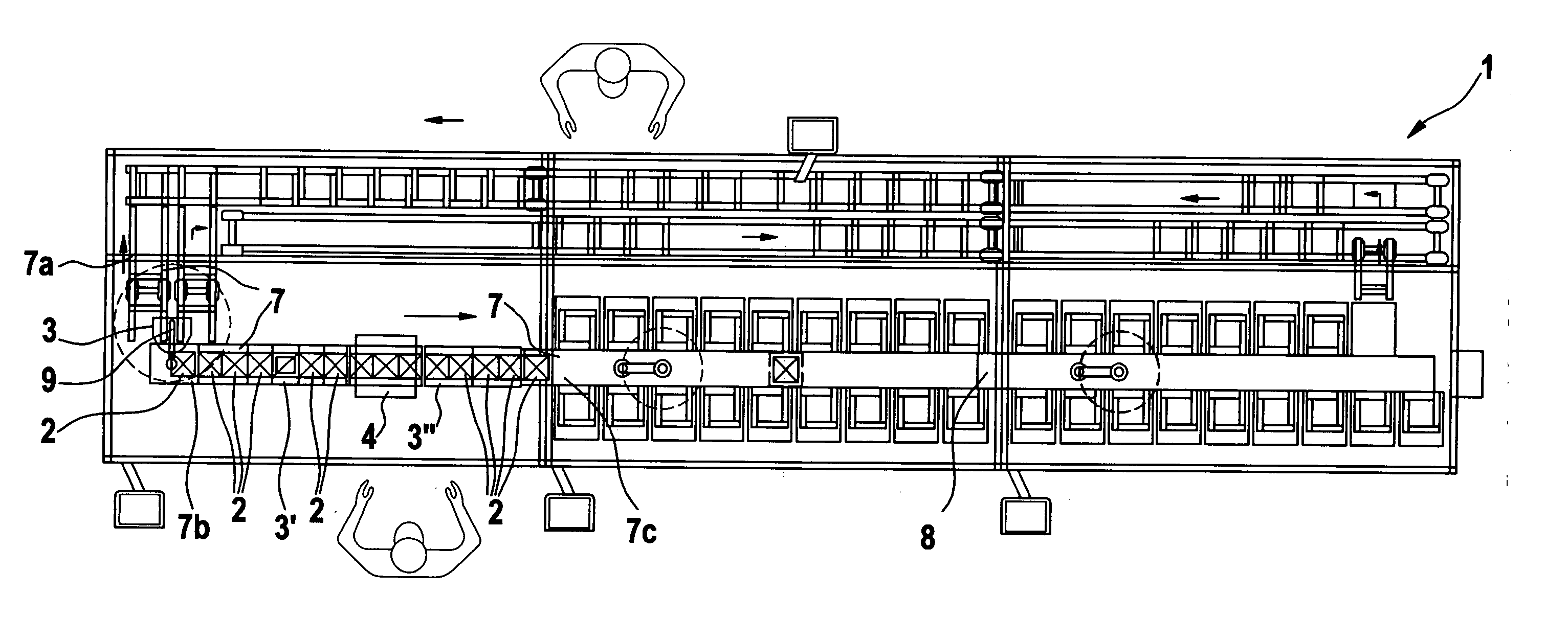
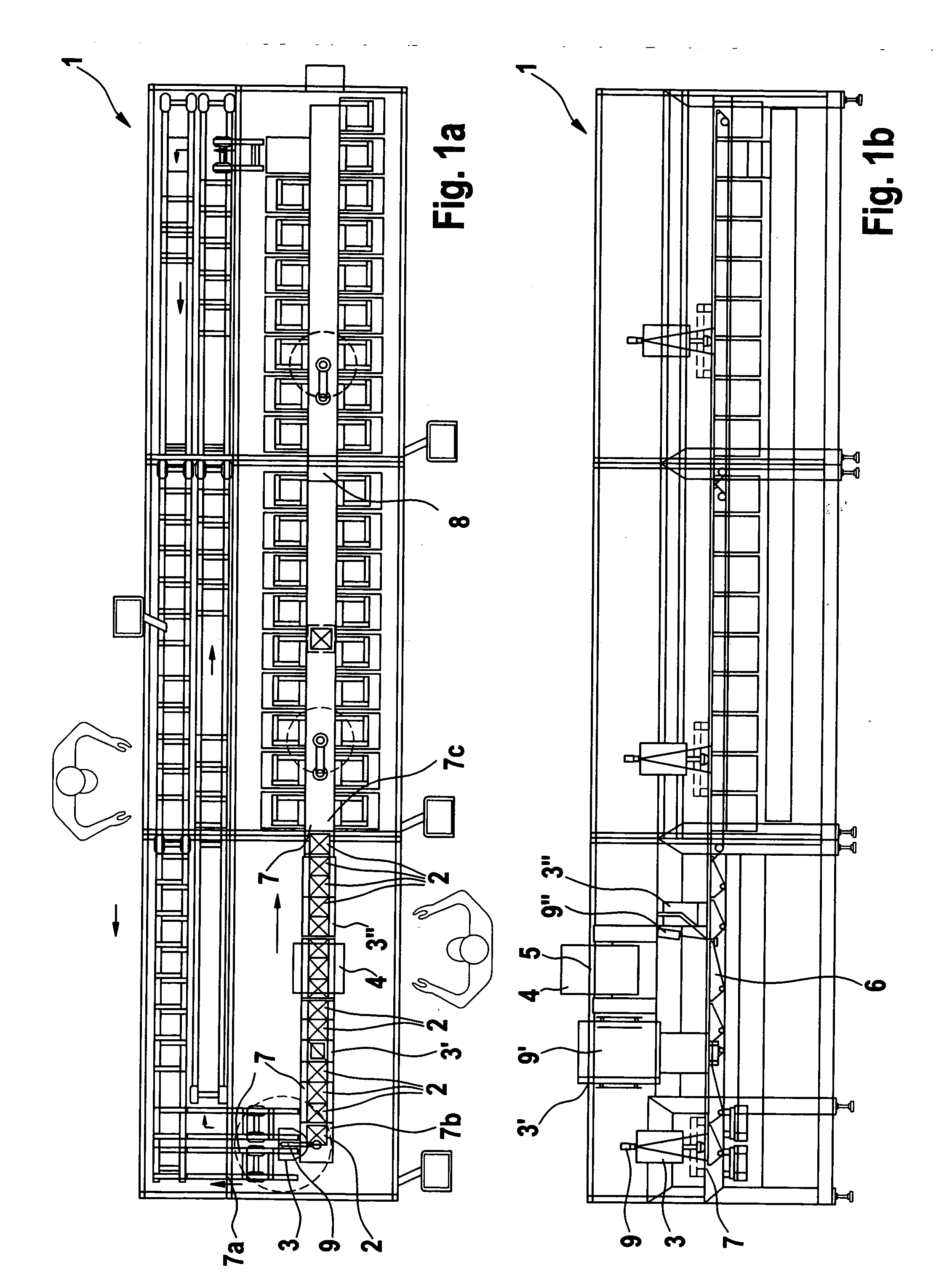
[0034] The embodiment shown in FIGS. 1a and 1b of a testing system 1 of the invention for optical and electrical monitoring of the production quality and / or for determining optical and electrical properties of solar cells 2 includes an optical checking device 3, 3′, 3″ for inspecting the solar cells 2, which is located in a test region of the testing system 1 and in the present exemplary embodiment, among other things, includes optical monitoring for correctness and completeness of printed conductor elements on the surface of the solar cells 2, checking for correct color and geometry of the solar cells 2, and three-dimensional optical monitoring, for instance for splinters or other foreign bodies located in the printed conductor elements. Also located in the test region of the testing system 1 is an electrical checking device 4 for monitoring the electrical functions of the solar cells 2. It includes an illumination device 5 for shining light on the light-sensitive surfaces of the s...


PUM


Abstract

A testing system for optical and electrical monitoring of a production quality and/or for determining optical and electrical properties of solar cells, comprising a first conveyor device for conveying the solar cells to a test region, a second conveyor device for moving the solar cells through the test region, a third conveyor device for conveying the solar cells out of the test region, an optical checking device located in the test region for visual checking of the solar, and an electrical checking device also located in the test region for checking electrical functions of the solar cells, the electrical checking device including an illumination device for shining light on light-sensitive surfaces of the solar cells and also including an electrical contacting device for picking up voltages and/or currents and electrical contacts of the solar cells, the first, second and third conveyor devices including a common, linear conveyor belt system which passes through the test region and has a vacuum suction device for holding the solar cells on a surface of a conveyor belt system.

Description

BACKGROUND OF THE INVENTION [0001] The invention relates to a testing system for optical and electrical monitoring of the production quality and / or for determining optical and electrical properties of solar cells. [0002] More particularly, it relates to a testing system of the above mentioned type which has a first conveyor device for conveying the solar cells to a test region, a second conveyor device for moving the solar cells through the test region, and a third conveyor device for conveying the solar cells out of the test region, and having an optical checking device, located in the test region, for visual checking of the solar cells, and an electrical checking device, also located in the test region, for checking the electrical functions of the solar cells, the electrical checking device including an illumination device for shining light on the light-sensitive surfaces of the solar cells and also includes an electrical contacting device for picking up voltages and / or currents a...

Claims


Application Information

Patent Timeline
IPC IPC(8): G01R31/28
CPCH02S50/10G01N21/8803Y02E10/50G01R31/40H01L21/677H01L31/042H01L31/18H02S40/38
Inventor MANZ, DIETER
Owner MANZ AUTOMATION
Why Eureka
Try Eureka