Method and apparatus for cell identification in wireless data networks

a wireless data network and cell identification technology, applied in the field of cell identification in wireless data networks, can solve the problems of ineffective approach to increase the capacity of the wireless network, loss of large part of the increase in spectral efficiency from frequency reuse, and inability to provide a medium, etc., to achieve the effect of improving the system capacity

Active Publication Date: 2006-05-18
CISCO TECH INC
View PDF24 Cites 12 Cited by
  • Summary
  • Abstract
  • Description
  • Claims
  • Application Information

AI Technical Summary

Benefits of technology

[0006] According to a first OFDM embodiment according to which each packet has a preamble that includes a plurality of short symbols, the last few short symbols are encoded such that each co-channel cell is given a different sequence. Then, the physical layer of the receiver can determine whether the packet is from an intra-cell or inter-cell transmitter. If the packet is from an inter-cell transmitter, the receiver can terminate processing at the very beginning of the packet. This minimizes or at least reduces the amount of time that the medium would be otherwise occupied.
[0010] Each of the embodiments has advantages and disadvantages. The second embodiment that uses the empty bits in the special field is simple to implement. However, not many of the bits in the special bits may be unused or reserved. Furthermore, more time is required before a determination is made regarding the cell of the packet than using the first embodiment. With the third embodiment, more bits may be available, but the third embodiment involves even more delay for cell identification.
[0013] Another aspect of the invention is a receiver that includes a signal processor with demodulation / re-modulation functionality and further processing to subtract out a signal determined to be an interfering signal. Consider such a receiver receiving a weak co-channel interfering signal prior to, but overlapping with, a desired signal, i.e., a signal designated for that receiver. Using the methods described above, the interfering signal may be ascertained to be from another cell, i.e., a co-channel interferer. The new signal processor in the receiver with demodulation / re-modulation functionality can subtract out the interfering signal. Subsequently, the signal can be processed for the desired signal without loss of the intended packet. Such an enhancement may further improve system capacity.

Problems solved by technology

However, this approach is not effective at increasing capacity in a wireless network such as one conforming to the IEEE 802.11 standard.
Therefore, if the region of coverage of a BSS (a “cell”) is sized such that typical performance at the boundary of the region of coverage of the BSS (the “cell boundary”) is at the highest data rate, then a signal transmitted at the lowest data rate can be received much farther away, and therefore might be a source of co-channel interference in a nearby cell.
So if the receiver is receiving an unintended co-channel signal, the medium is not available the entire time the receiver is processing the unintended co-channel signal.
Much of the increase in spectral efficiency from frequency reuse may be lost due to such co-channel interference.
However, not many of the bits in the special bits may be unused or reserved.
Furthermore, more time is required before a determination is made regarding the cell of the packet than using the first embodiment.
The MAC address comes along relatively late in the packet, so it will take the receiving STA a relatively long time to recover that information.
The MAC address information is often coded at a very high data rate, up to 54 Mbps, so that the receiving STA may not be able to recover the required information at all.
A STA receiving these bits from a co-channel interferer may be attempting to decode the bits in a weak signal, and therefore may make errors in so decoding the information.
More complex restoral methods typically rely upon reconstruction of the received signal.

Method used


Image

  • Method and apparatus for cell identification in wireless data networks
  • Method and apparatus for cell identification in wireless data networks
  • Method and apparatus for cell identification in wireless data networks

Examples


Embodiment Construction

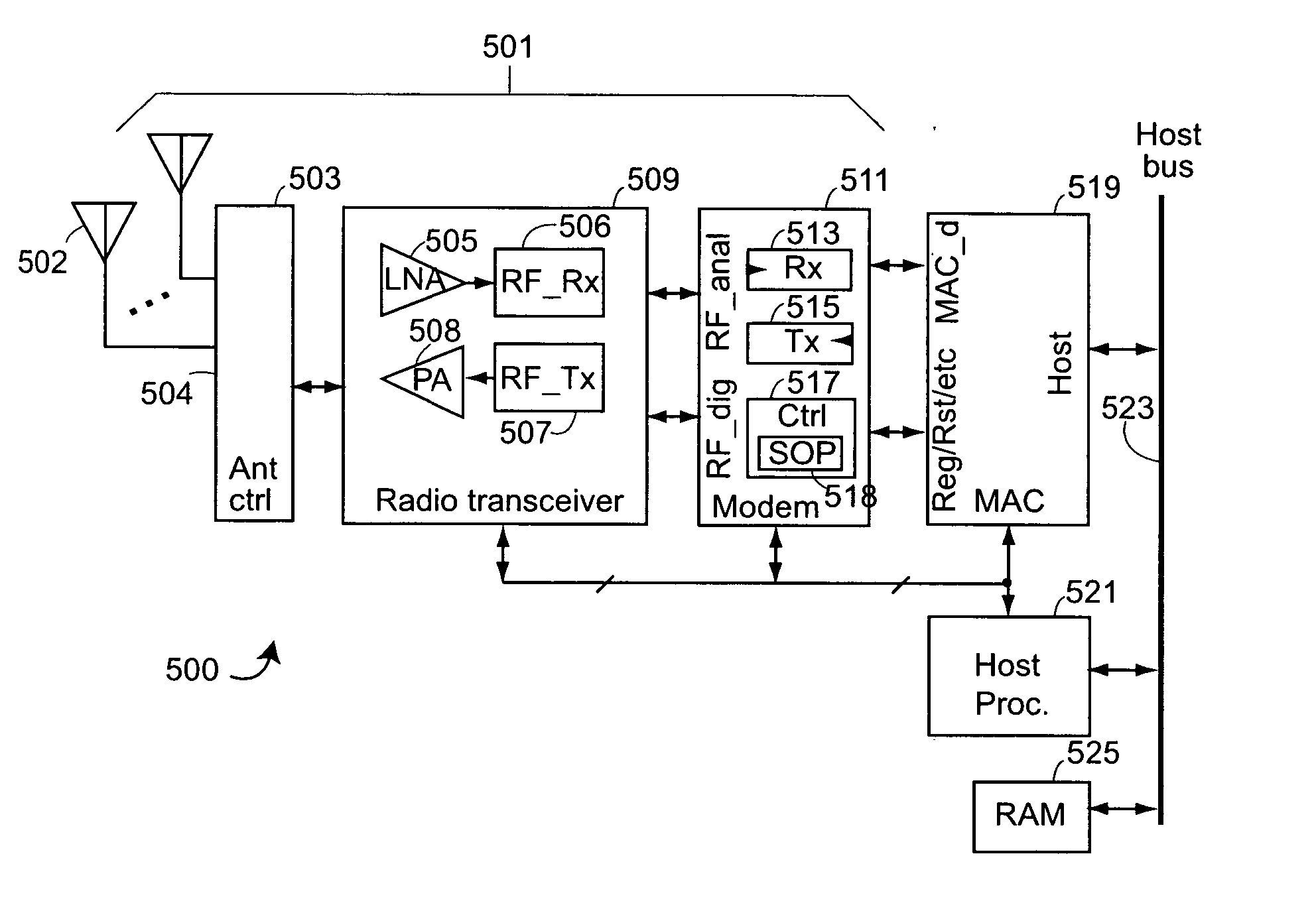
[0024] One aspect of the invention provides for ascertaining, at the physical layer level, whether or not a packet received at a station of a cell of a wireless network is from another station of the cell. A cell in the context of the invention is a set of wireless stations of a wireless network that are meant to communicate with each other. An example of a cell is an infrastructure network in which there is one station, called the access point, through which each station of the cell communicates. Another example of a cell is an ad-hoc network of stations that communicate with each other.

[0025] Each such cell is designed to have an area of coverage. To cover a large area, e.g., a building, many such cells are used.

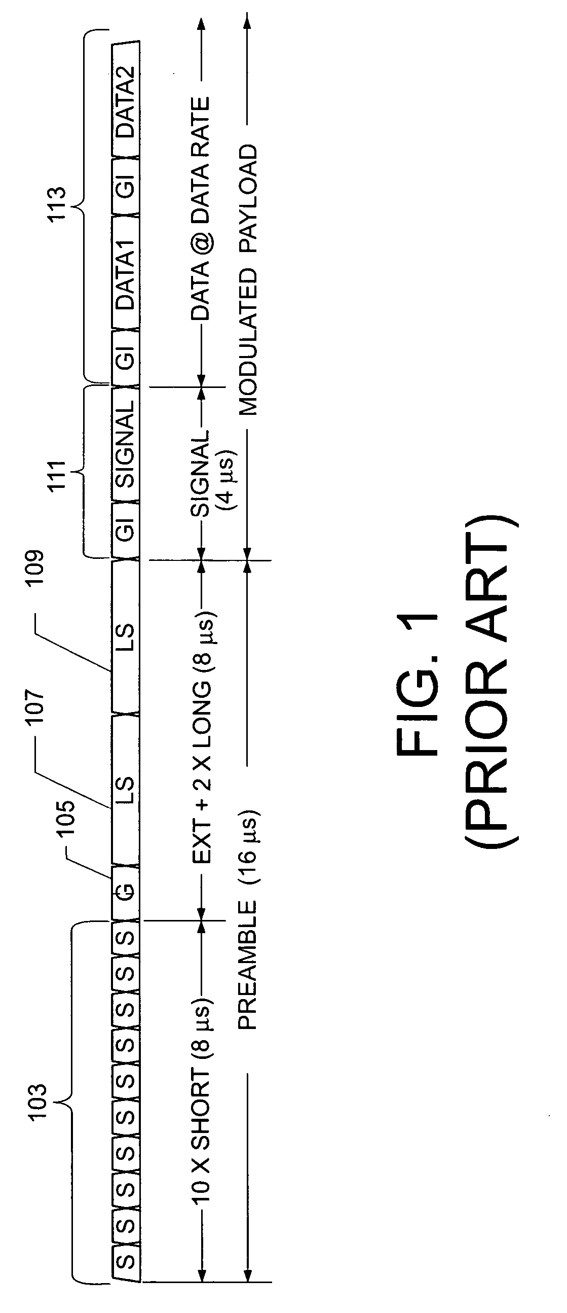
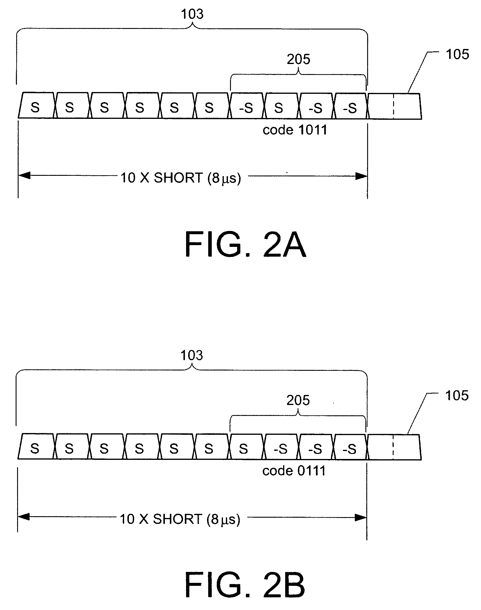
[0026] The description described aspects of the invention applied to wireless local area networks that conform to the IEEE 802.11 standard. In particular, this description will be presented applied to the OFDM variants of the IEEE 802.11 standard, in particular applied t...


PUM


Abstract

A method including wirelessly receiving a packet at a wireless station belonging to a cell of a wireless network, the network for communicating according to a wireless network standard, each transmitting station of the cell able to transmit a packet that includes cell identification information; and ascertaining at the physical layer level whether or not the received packet is from another station of the cell by ascertaining whether or not the received packet includes the cell identification information of the cell.

Description

RELATED PATENT APPLICATIONS [0001] The present application is a continuation of U.S. patent application Ser. No. 10 / 676,878 filed on Sep. 30, 2003 titled METHOD AND APPARATUS FOR CELL IDENTIFICATION IN WIRELESS DATA NETWORKS. The contents of U.S. patent application Ser. No. 10 / 676,878 are incorporated herein by reference.BACKGROUND [0002] Wireless networks that have an infrastructure that includes a central station through which all other wireless stations communicate are now in common use for wireless data networks such as wireless local area networks (WLANs). Such infrastructure networks resemble cellular wireless networks that have a set of cells, the client stations within each communicating via a central station sometimes called a base station. The IEEE 802.11 standard in all its variations, for example, is now in common use for WLANs, and defines an infrastructure network having an access point (AP) through which all other stations (called client stations herein) of the same i...

Claims


Application Information

Patent Timeline
Patent Type & Authority Applications(United States)
IPC IPC(8): H04Q7/24H04B7/00H04J3/24H04J11/00H04L12/28H04W24/02H04W84/12
CPCH04W24/02H04W84/12
Inventor DOUGLAS, BRETTON LEEPERAHIA, ELDAD
Owner CISCO TECH INC
Why Eureka
Try Eureka