Method for reducing noise in images

a noise reduction and image technology, applied in the field of image noise reduction, can solve the problems of deteriorating image quality, affecting the image quality, so as to achieve the effect of reducing image noise properly, reducing image quality, and reducing luminance differences small and small

Inactive Publication Date: 2006-05-18
NORITZ CORP
View PDF22 Cites 40 Cited by
  • Summary
  • Abstract
  • Description
  • Claims
  • Application Information

AI Technical Summary

Benefits of technology

[0019] In the mosquito noise reducing process, not only the second luminance component image data is created, but also the third luminance component image data is created by combining the corrected edge image data created from the edge image data with the second luminance component image data. This is because only a small luminance difference can be smoothed while not greatly smoothing a contour of a large luminance difference, that is, mosquito noise can be reduced without deterioration of the image quality.
[0020] Then, the third luminance component image data and the first color-difference component image data are finally outputted. Thus, in the block noise reducing process, the image is previously divided into blocks and the boundaries of the blocks are smoothed. Therefore, contours on the background of an image are not erroneously recognized as boundaries and subjected to the block noise reducing process. Thus, block noise is properly reduced without deterioration of the image quality. In the m...

Problems solved by technology

Particularly, quantization errors in quantization and reverse quantization deteriorate the quality of the regenerated image.
The larger the quantization step width (or the larger the compression rate), the greater the number of quantization errors caused and hence the more noticeable the deterioration of the quality of the regenerated image signal.
These image noise reducing processes are in certain senses achieved by deterioration of an original image, thus causing...

Method used


Image

  • Method for reducing noise in images
  • Method for reducing noise in images
  • Method for reducing noise in images

Examples


Embodiment Construction

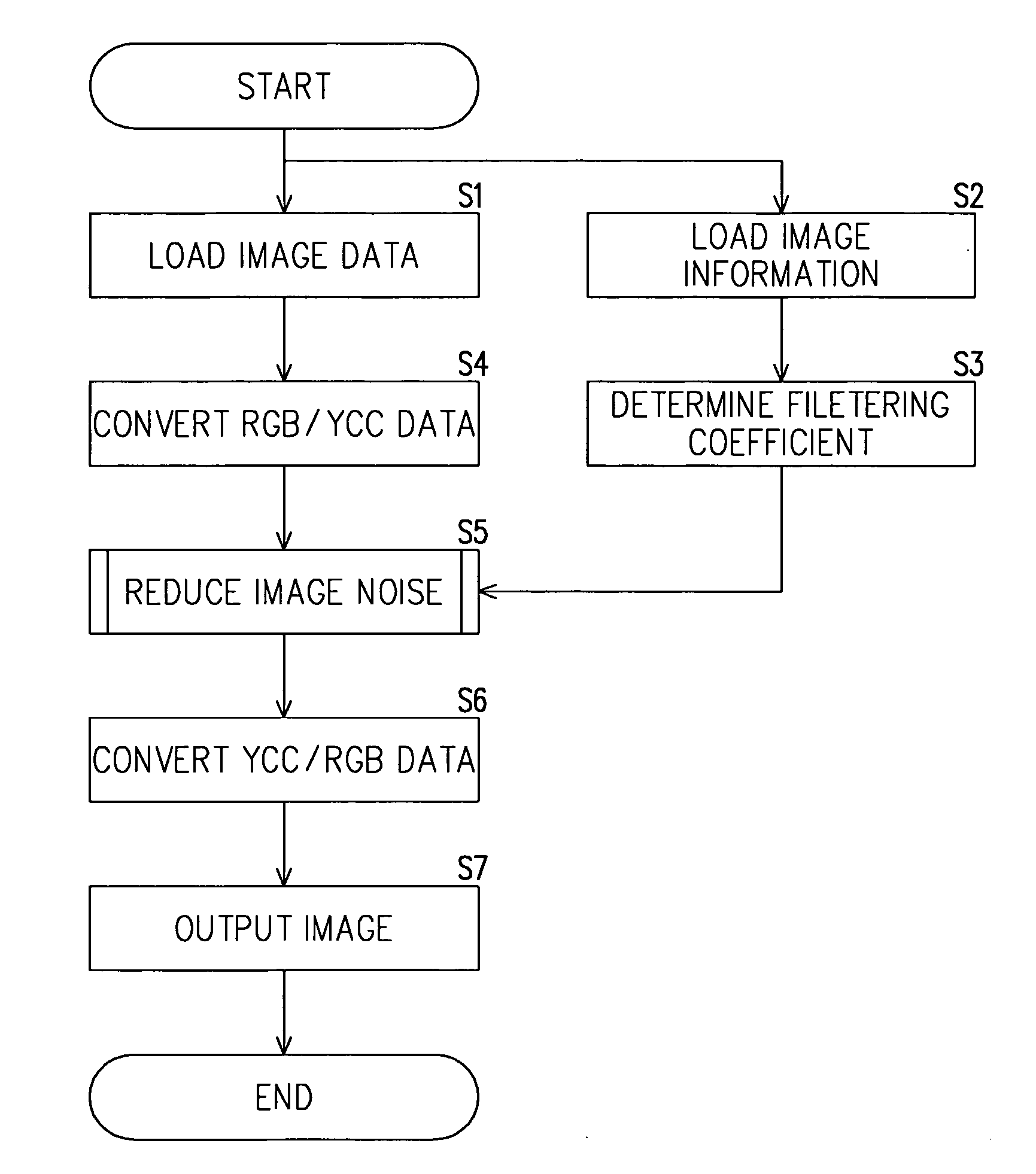
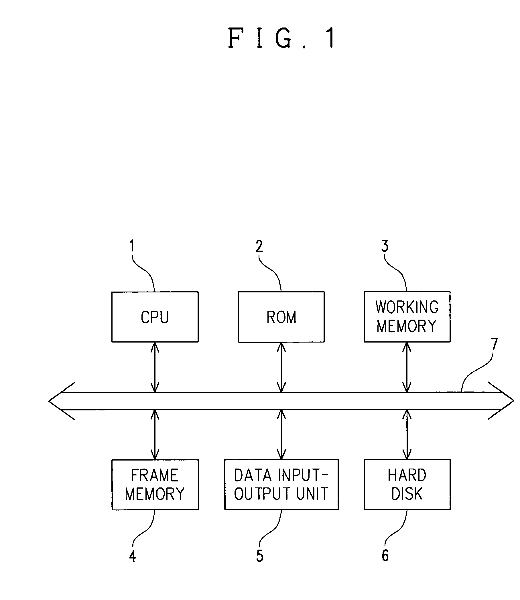
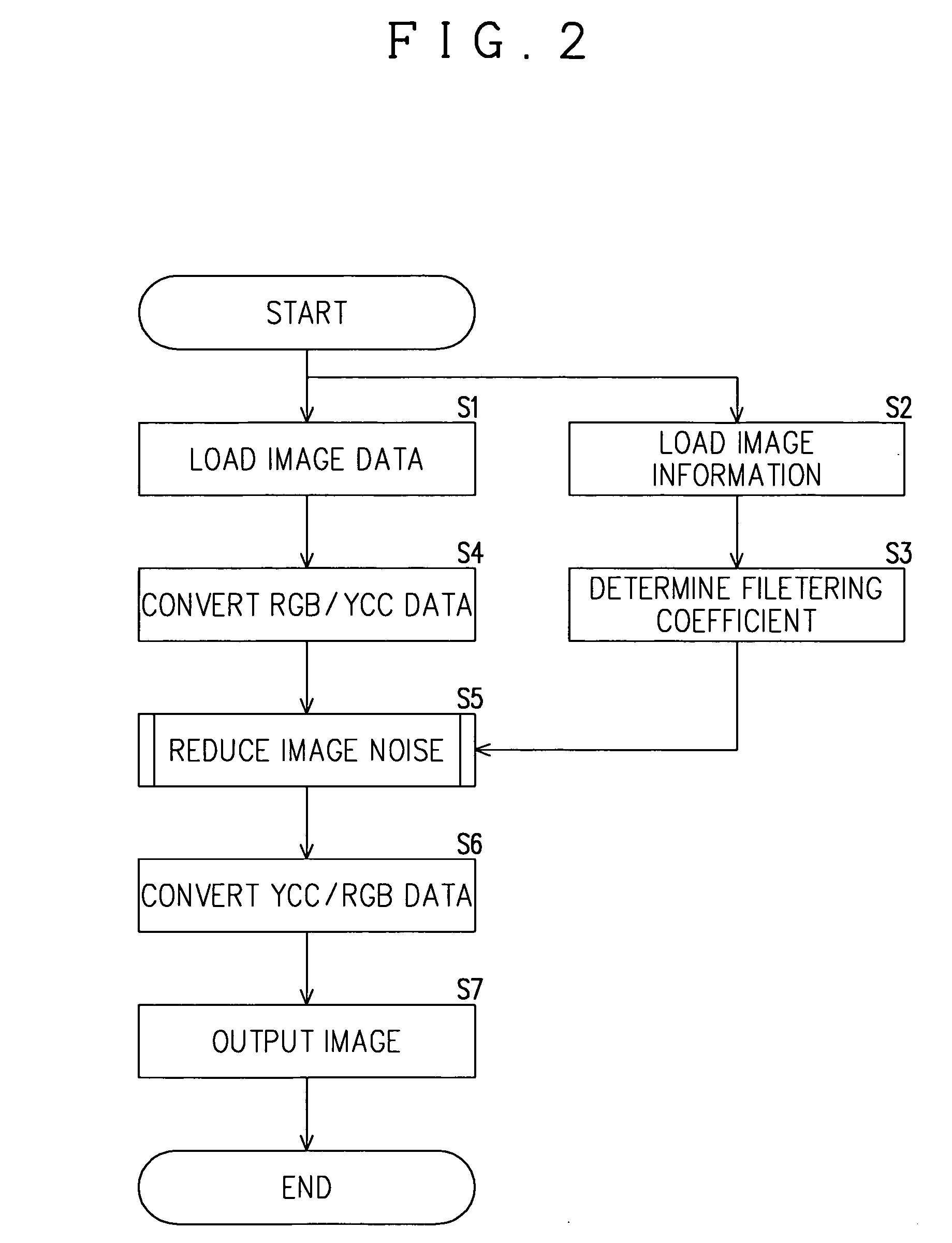
[0043] Now, the description will be made for the structure of an image processing apparatus that realizes the method of reducing noise in images according to one embodiment of the present invention with reference to FIG. 1. An image processing apparatus comprises a computer with a CPU 1, a ROM 2, a working memory 3, a frame memory 4, a data input-output unit 5 and a hard disk 6, which are all connected to a bus 7. The ROM 2 serves to store an image noise reducing program, other computer programs and various parameters, while the working memory 3 that is required for realizing control by the CPU contains such as a buffer and register. The CPU 1 performs various calculations and processes based on computer programs stored in the ROM 2.

[0044] The frame memory 4 is a memory for storing image data obtained by decoding a still image compressed and encoded in JPEG format. Image data (R, G, B) inputted in the data input-output unit 5 are once stored respectively in separate frame memories ...


PUM


Abstract

There is provided a method of reducing block noise, mosquito noise and other image noises in an image by a filtering process using a smoothing filter, which block noise, mosquito noise and other image noises being caused at the time of decoding encoded, compressed image data on a block-by-block basis. The method includes changing the extent or intensity of the image noise reduction in the filtering process in a continuous or stepwise manner according to an output size or expansion rate of an image to be outputted to printer paper, photographic paper or other output media, thereby allowing the extent or intensity of the image noise reduction to be increased as the output size or expansion rate of the image increases. This method is capable of allowing the extent of the image noise reduction applied to image data to be perceived in a similar fashion, irrespective of the output size.

Description

CROSS REFERENCE TO RELATED APPLICATION [0001] This application claims priority from Japanese Patent Application No. 2004-329260, which is incorporated herein by reference. BACKGROUND OF THE INVENTION [0002] 1. Field of the Invention [0003] The present invention relates to a method of reducing block noise, mosquito noise and other noises in an image, which noises are caused at the time of decoding encoded, compressed image data on a block-by-block. [0004] 2.Related Art [0005] In order to produce a highly compressed image data, an orthogonally transformation encoding as a highly effective image data compression technique is generally employed. This technique in summary involves dividing an input image signal into blocks of such as 8×8 pixels by a blocking circuit, subjecting the divided blocks to an orthogonal transformation process by an orthogonal transformation circuit to generate a frequency component signal, subjecting the orthogonally transformed data to a linear quantization pr...

Claims


Application Information

Patent Timeline
IPC IPC(8): G06K9/40G06T9/00H04N1/409H04N1/41H04N19/00H04N19/117H04N19/136H04N19/14H04N19/167H04N19/176H04N19/186H04N19/196H04N19/44H04N19/60H04N19/625H04N19/63H04N19/80H04N19/86H04N19/91
CPCG06T2207/10024G06T5/002G06T5/20H04N19/86H04N19/136H04N19/186H04N19/85H04N19/117
Inventor IZUMI, KEISUKE
Owner NORITZ CORP
Why Eureka
Try Eureka