Roller bearing assembly

Inactive Publication Date: 2006-05-18
NTN CORP
View PDF13 Cites 17 Cited by
  • Summary
  • Abstract
  • Description
  • Claims
  • Application Information

AI Technical Summary

Benefits of technology

[0047] In the case of this fourth assembling method, with no need to use the alternatively constrictable and expandable jig such as, for example, a collet chuck, to allow an insertion of a pushing jig, mere insertion of the roller retainer inside the guide jig referred to above results in assemblage of the roller bearing assembly. In such case, the flexure deformation of the roller retainer is minimal and an undesirable reduction

Problems solved by technology

Accordingly, not only is the machining limit of the roller retainer encountered with, but the strength of the roller retainer tends to decrease.
Accordingly, when an attempt is made to reduce the pitch between the neighboring rollers to render the resultant roller and retainer assembly to have an increased load bearing capacity, the plate thickness cannot be increased with no decrease of the strength, rendering the strength of the retainer to be low.
On the other hand, the roller and retainer assembly disclosed in the second mentioned Japanese patent document, that is, of the structure in which the split region is employed in the inner member at a location circumferentially thereof

Method used


Image

  • Roller bearing assembly
  • Roller bearing assembly
  • Roller bearing assembly

Examples


Example

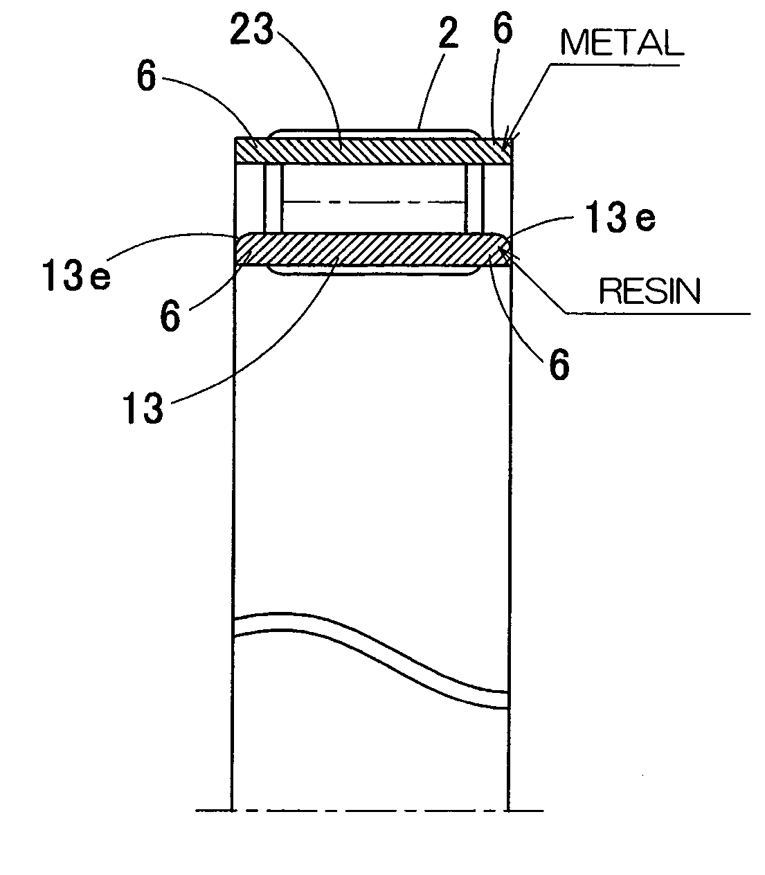
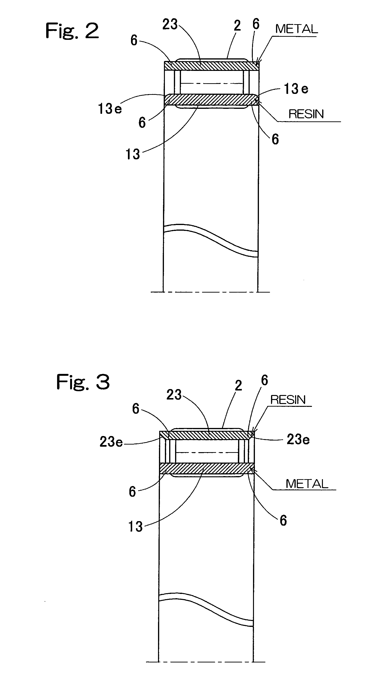
[0090] Referring now to FIG. 2 showing the second embodiment of the present invention, the inner roller retainer 13 made of the synthetic resin has radially outer edge portions 13e which may be tapered or be so shaped as to be arcuately rounded in section to represent an axially outwardly constricted edge portion. The axially outwardly constricted edge portions are effective to facilitate a smooth insertion of the inner roller retainer 13 in a direction inwardly of the circular row of the rollers 2 during assemblage, with the assemblability further increased consequently.

Example

[0091] In the third embodiment of the present invention shown in FIG. 3, of the inner and outer roller retainers 13 and 23, the inner roller retainer 13 is made of a metallic material and the outer roller retainer 23 is made of a synthetic resin. Even in such case, as compared with the inner and outer roller retainers 13 and 23 both made of a synthetic resin, the retainer strength as a combination type roller bearing can increase. Also, even though the inner roller retainer 13 is made of a metallic material, since the outer roller retainer 23 is made of a synthetic resin, the elastic deformation thereof can be effectively utilized to facilitate incorporation of the rollers 2.

[0092] Where the outer roller retainer 23 is made of a synthetic resin, opposite radially inner edge portions 23e of this outer roller retainer 23 may be so shaped as to be arcuately rounded in section to represent an axially outwardly constricted edge portion. Thereby, in a manner similar to the embodiment sho...

Example

[0093] The fourth embodiment shown in FIG. 4 is such that in the roller bearing assembly, in which the outer roller retainer 23 is made of a metallic material as is the case with that in the first embodiment, the outer roller retainer 23 has its opposite ends formed with radially inwardly extending collars 23f. Each of the collars 23f has an inner diameter smaller than the pitch circle diameter PCD. On the other hand, the inner roller retainer 13 is made of a synthetic resin and has radially outer edge portions 13e each tapered or be so shaped as to be arcuately rounded in section to represent an axially outwardly constricted edge portion.

[0094] Where the roller retainer 23 made of the metallic material is provided with the collars 23f as hereinbefore described, the strength of the roller retainer 23 can be further increased. Also, even where any interfering object is present in a side edge of the roller bearing assembly, the collars 23f displace such interfering object and, theref...


PUM


Abstract

To provide a roller bearing assembly that can provide a high load bearing capacity and in which the strength of roller retainers can be increased, the roller bearing assembly includes inner and outer roller retainers (13, 23) each having a plurality of circumferentially arranged pockets (4), and a circular row of rollers (2) received in part within the pockets in the inner roller (13) and in part within the pockets in the outer roller (23). The inner roller retainer (13) has pillars (5) each left between the neighboring pockets to retain the circular row of the rollers from radially inwardly and having an outer diameter smaller than the diameter of the pitch circle PCD of the circular row of the rollers. The outer roller retainer (23) has pillars (5) each left between the neighboring pockets to retain the circular row of the rollers from radially outwardly and having an inner diameter greater than the pitch circle diameter PCD. One of the outer and inner roller retainers is made of a metallic material while the other thereof is made of a resinous material.

Description

BACKGROUND OF THE INVENTION [0001] 1. Field of the Invention [0002] The present invention relates to a roller bearing assembly that can be applied where a large load bearing capacity is required within a limited space, such as including a bearing assembly for supporting big and small ends of a connecting rod in an engine, a bearing assembly for a transmission, a bearing assembly for use in car air conditioners, a bearing assembly for use with a seat reclining mechanism and a bearing assembly for use in reduction gear units. [0003] 2. Description of the Prior Art [0004] The roller bearing assembly has hitherto been well known, of a type in which neither an inner race nor an outer race is employed and a row of rolling elements are held in direct contact with inner and outer peripheral surfaces of operating elements of a device or equipment. This type of roller bearing assembly is generally referred to as a roller and retainer assembly or a caged roller assembly. In order to avoid acci...

Claims


Application Information

Patent Timeline
IPC IPC(8): F16C33/48
CPCF16C33/4611F16C33/56F16C43/08F16C2240/84F16C19/26
Inventor KONO, SHINGOOBAYASHI, KOUSUKEAKAMATSU, HIDEKI
Owner NTN CORP
Why Eureka
Try Eureka