Magnetic resonance imaging device and data processing method for magnetic resonance imaging device

a magnetic resonance imaging and data processing technology, applied in the field of magnetic resonance imaging apparatuses, can solve the problems of non-uniformity of image data, and non-uniformity of signal intensities in the z-axis direction of the device coordinate system, so as to accurately estimate the sensitivity distribution of the rf coil and correct the unevenness of image data. the effect of signal intensity

Active Publication Date: 2006-05-18
TOSHIBA MEDICAL SYST CORP
View PDF4 Cites 31 Cited by
  • Summary
  • Abstract
  • Description
  • Claims
  • Application Information

AI Technical Summary

Benefits of technology

[0055] In such magnetic resonance imaging apparatuses and data processing methods for a magnetic resonance imaging apparatus, it is possible to estimate a sensitivity distribution of the RF coil accurately on the basis of image data obtained by implementation of sensitivity pre-scan and correct luminance of image data obtained by implementation of main s

Problems solved by technology

However, when the RF coil 4 is constituted by the phased-array coil including the plural surface coils, because of non-uniformity of sensitivities of the respective surface coils constituting the RF coil 4, non-uniformity occurs not only in signal intensities of the NMR signals but also in signal intensities of the image data simply obtained by the reconstruction processing according to the Fourier transformation of the raw data.
Thus, luminance unevenness occurs in the image data.
In addition, non-uniformity occurs in signal intensities in a Z-axis direction of a device coordinate system because of not only a sensitivity distribution but also an arrangement characteristic of the respective surface coils of the phased-array coil.
However, in the conventional magnetic resonance imaging apparatus 1, non-uniformity of signal intensities due to the misregistration of image data in the sensitivity pre-scan and the arrangement characteristic of the surface coils is not taken into account.
As a result, in the conventional magnetic resonance imaging apparatus 1, a problem occurs in that accuracy of the sensitivity distribution of the phased-array coil estimated by the sensitivity pre-scan is not obtained sufficiently and luminance of the reconstructed image obtained by the main scan cannot be corrected at sufficient accuracy.
However, in particular, non-uniformity in sensitivities of the surface coils in the phased-array coil serving as coils adapted to respective purposes is large, which affects image data.
Therefore, it is necessary to correct the non-uniformity in signal intensi

Method used


Image

  • Magnetic resonance imaging device and data processing method for magnetic resonance imaging device
  • Magnetic resonance imaging device and data processing method for magnetic resonance imaging device
  • Magnetic resonance imaging device and data processing method for magnetic resonance imaging device

Examples


first embodiment

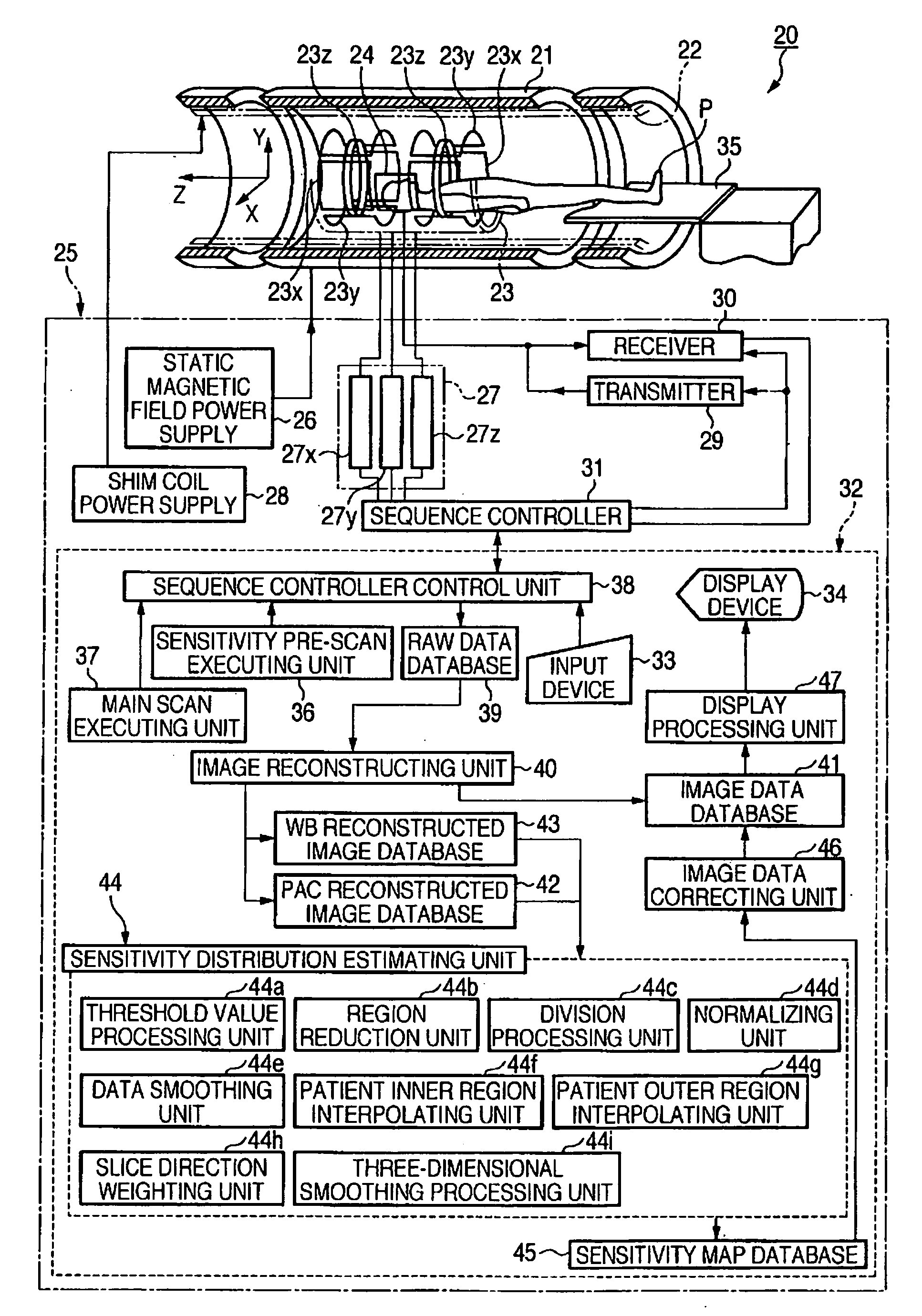
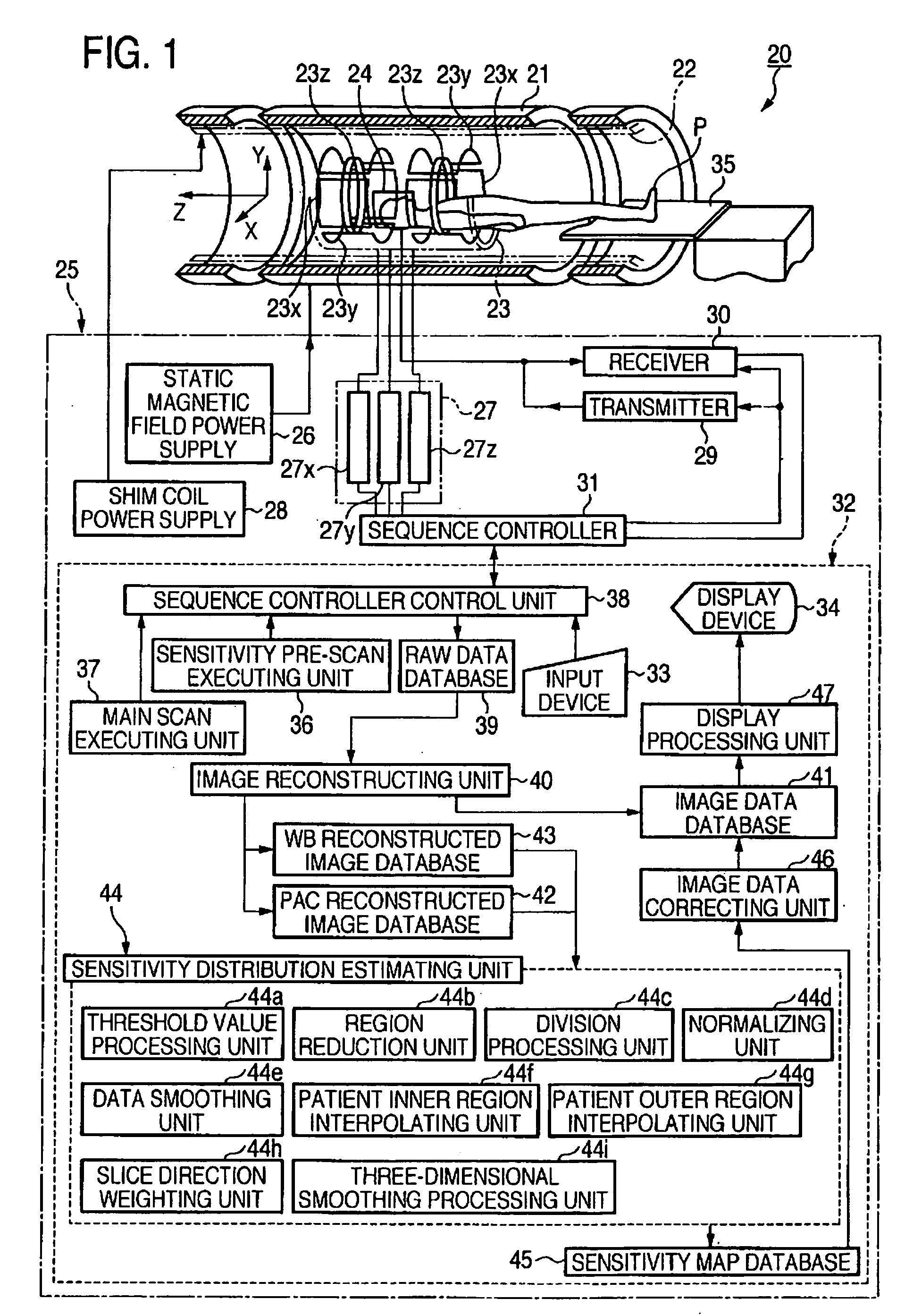
[0086]FIG. 1 is a functional block diagram showing the magnetic resonance imaging apparatus according to the invention.

[0087] A magnetic resonance imaging apparatus 20 has a structure in which a cylindrical magnet for static magnetic field 21 for forming a static magnetic field, a shim coil 22 provided inside this magnet for static magnetic field 21, and a gradient magnetic field coil unit 23 and an RF coil 24 are incorporated in a not-shown gantry.

[0088] The magnetic resonance imaging apparatus 20 includes a control system 25. The control system 25 includes a static magnetic field power supply 26, a gradient magnetic field power supply 27, a shim coil power supply 28, a transmitter 29, a receiver 30, a sequence controller 31, and a computer 32. The gradient magnetic field power supply 27 of the control system 25 includes an X-axis gradient magnetic field power supply 27x, a Y-axis gradient magnetic field power supply 27y, and a Z-axis gradient magnetic power supply 27z. The comput...

second embodiment

[0173]FIG. 14 is a block diagram showing the magnetic resonance imaging apparatus according to the invention.

[0174] A magnetic resonance imaging apparatus 20A shown in FIG. 14 is different from the magnetic resonance imaging apparatus 20 shown in FIG. 1 in detailed structures of the RF coil 24 and the receiver 30 and functions of the computer 32. Since the structures of the other components and the actions are not substantially different from those in the magnetic resonance imaging apparatus 20 shown in FIG. 1, the identical components are denoted by the same reference numerals and signs and are not explained.

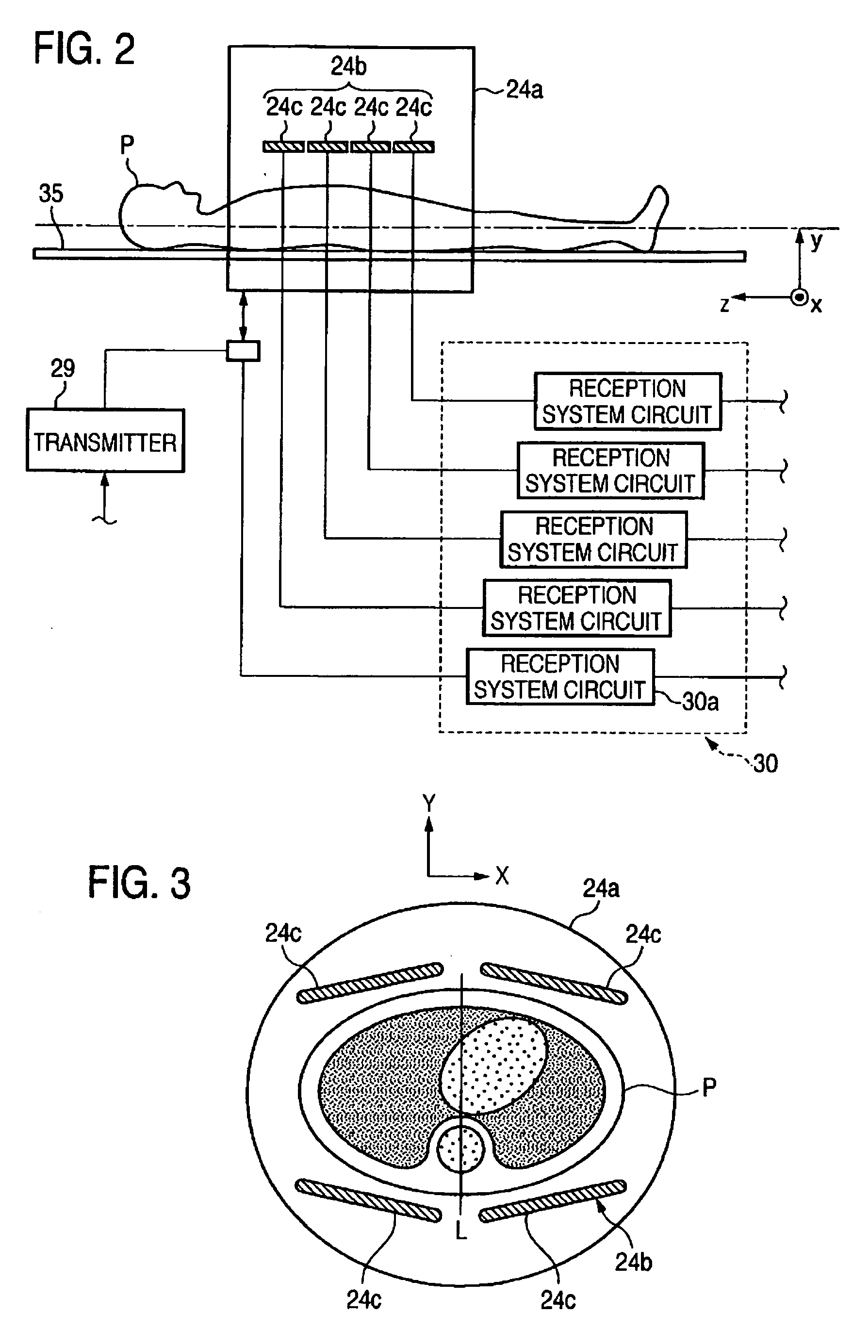
[0175]FIG. 15 is a detailed diagram showing an example of the RF coil 24 and the receiver 30 shown in FIG. 14.

[0176] The RF coil 24 includes the WB coil 24a for transmission of a radiofrequency signal and the phased-array coil 24b serving as a main coil that is a coil for receiving an NMR signal. The phased-array coil 24b includes the plural surface coils 24c.

[0177] On the o...

third embodiment

[0237]FIG. 23 is a functional block diagram showing the magnetic resonance imaging apparatus according to the invention.

[0238] A magnetic resonance imaging apparatus 20B shown in FIG. 23 is different from the magnetic resonance imaging apparatus 20A shown in FIG. 14 in that the computer 32 also functions as an imaging condition for shimming setting unit 60. Since the other components and actions are not substantially different from those of the magnetic resonance imaging apparatus 20A shown in FIG. 14, the identical components are denoted by the same reference numerals and signs and are not explained.

[0239] The computer 32 of the magnetic resonance imaging apparatus 20B also functions as the imaging condition for shimming setting unit 60. The imaging condition for shimming setting unit 60 has a function of setting an imaging condition in shimming, which is carried out to correct spatial non-uniformity of a static magnetic field, and gives the imaging condition to the sensitivity pr...


PUM


Abstract

A magnetic resonance imaging apparatus 20 includes a scan executing unit that executes scan to generate sensitivity map data of an RF coil 24, a region reduction unit 44b that applies region reduction to a signal region near a no-signal region of image data obtained by the scan, a sensitivity map data generating unit 44 that generates sensitivity map data using image data after the region reduction, and a smoothing processing unit 44i that applies three-dimensional smoothing filter to the sensitivity map data.

Description

TECHNICAL FIELD [0001] The present invention relates to a magnetic resonance imaging apparatus that images a patient using a nuclear magnetic resonance signal and a data processing method for the magnetic resonance imaging apparatus. In particular, the invention relates to a magnetic resonance imaging apparatus that corrects non-uniformity in luminance and signal values of image data due to a sensitivity distribution of a reception coil and a data processing method for the magnetic resonance imaging apparatus. BACKGROUND ART [0002] Conventionally, as a monitoring apparatus in medical spots, a magnetic resonance imaging (MRI) apparatus 1 shown in FIG. 24 has been used (see, for example, Japanese Patent No. 3135592). [0003] The magnetic resonance imaging apparatus 1 is an apparatus that forms gradient magnetic fields in X-axis, Y-axis, and Z-axis directions in an imaging region of a patient P, who is set inside a cylindrical magnet for static magnetic field 2 forming a static magnetic...

Claims


Application Information

Patent Timeline
IPC IPC(8): A61B5/05A61B5/055G01R33/20G01R33/32G01R33/3415G01R33/36G01R33/56
CPCG01R33/246G01R33/5659G01R33/3415
Inventor UCHIZONO, SHINICHIMACHIDA, YOSHIOICHINOSE, NOBUYASU
Owner TOSHIBA MEDICAL SYST CORP
Why Eureka
Try Eureka