Electronically scanned optical coherence tomography with frequency modulated signals

a frequency modulated signal and optical coherence tomography technology, applied in the field of optical measurement methods and systems, can solve the problems of large, complex, power-consuming, and limited speed of these systems

Inactive Publication Date: 2006-05-18
SCI MED LIFE SYST
View PDF37 Cites 54 Cited by
  • Summary
  • Abstract
  • Description
  • Claims
  • Application Information

AI Technical Summary

Problems solved by technology

This is because the portion of the sample beam that is reflected back to the catheter from a certain depth in the body constructively interferes with the diffraction beam at a certain spatial position.
However, the speed of these systems are limited by mechanical factors such as mass, the electromechanical properties of the piezoelectric material and the need to scan at a constant velocity.
These limitations translate into scanning rates that are considerably slower than true video rate, such that real time viewing cannot be achieved.
However, grating generated OCT systems require a large number of parallel electronic channels, which are very large, complex and power consuming.

Method used


Image

  • Electronically scanned optical coherence tomography with frequency modulated signals
  • Electronically scanned optical coherence tomography with frequency modulated signals
  • Electronically scanned optical coherence tomography with frequency modulated signals

Examples


Embodiment Construction

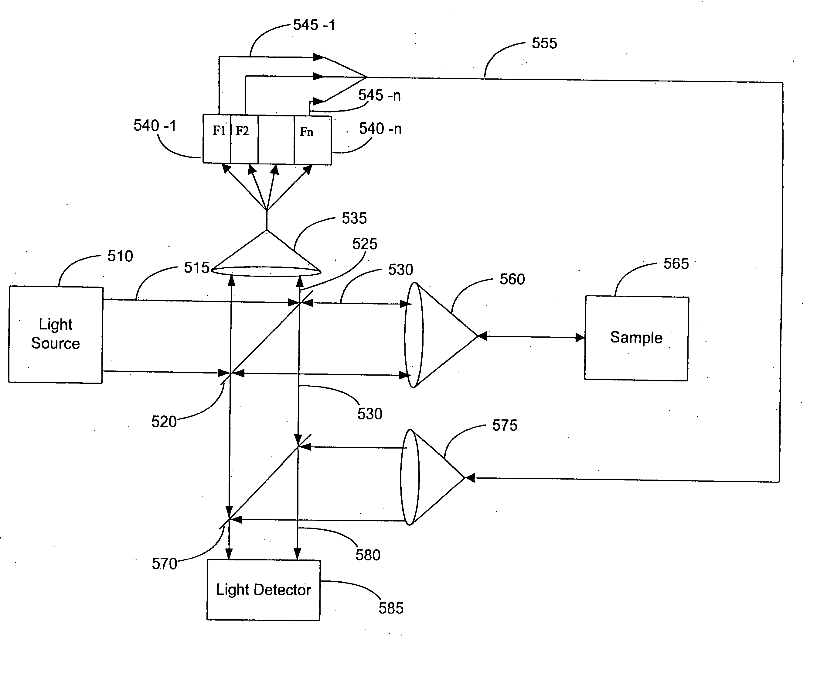
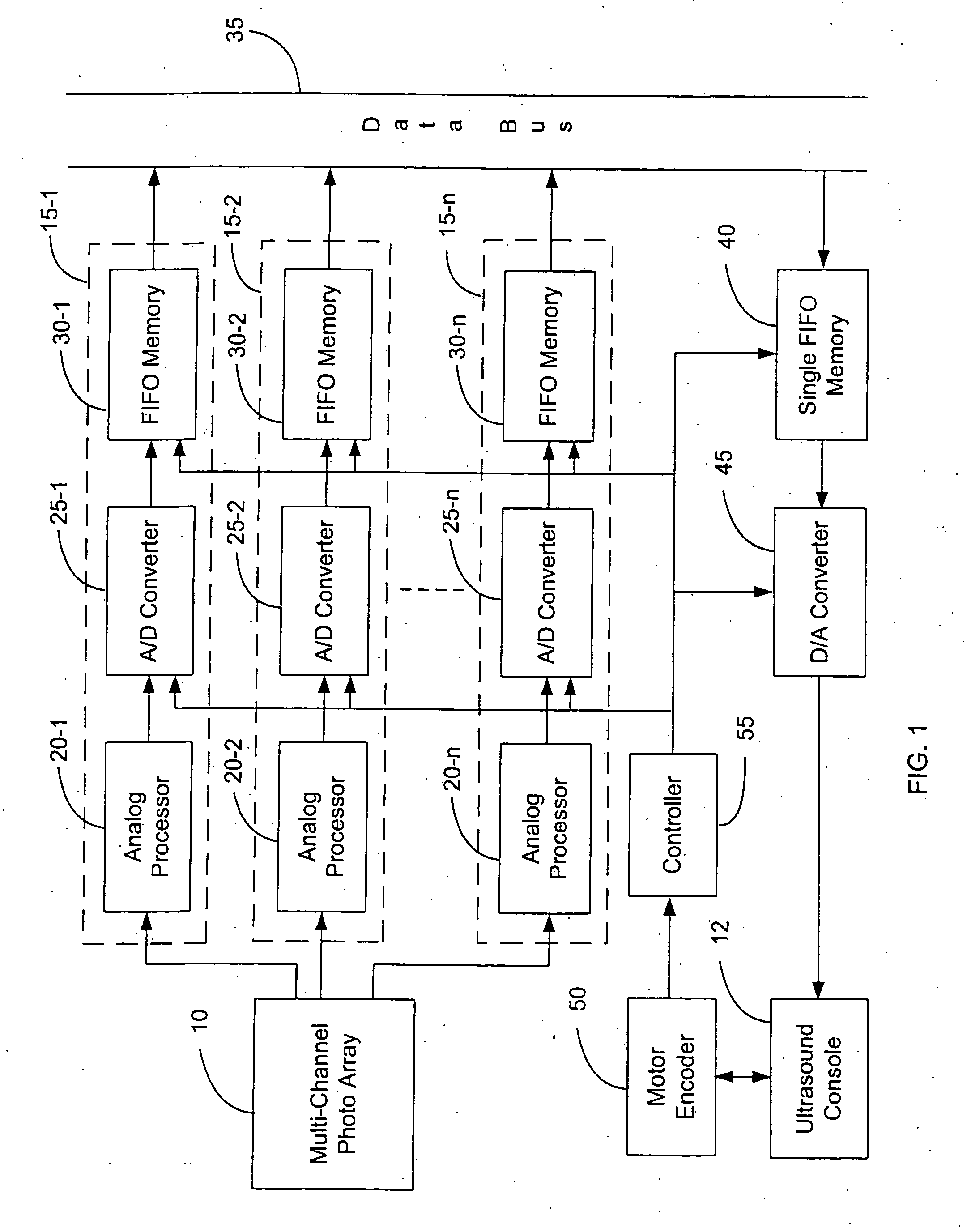
[0038]FIG. 1 shows an example embodiment of an electronics interface between an OCDR system and an ultrasound console. The electronics interface system is coupled between a multi-channel photo array 10 of an OCDR system and an ultrasound console 12. The photo array 10 comprises a plurality of photo detectors (not shown), e.g., 256 photo detectors. Each photo detector of the photo array 10 outputs a signal carrying image brightness information for a certain image depth. The photo detectors may be photodiodes, Charge Coupled Devices (CCDs), or the like. The photo array outputs a plurality of parallel channels, where each one of the parallel channels corresponds to the output of one of its photo detectors.

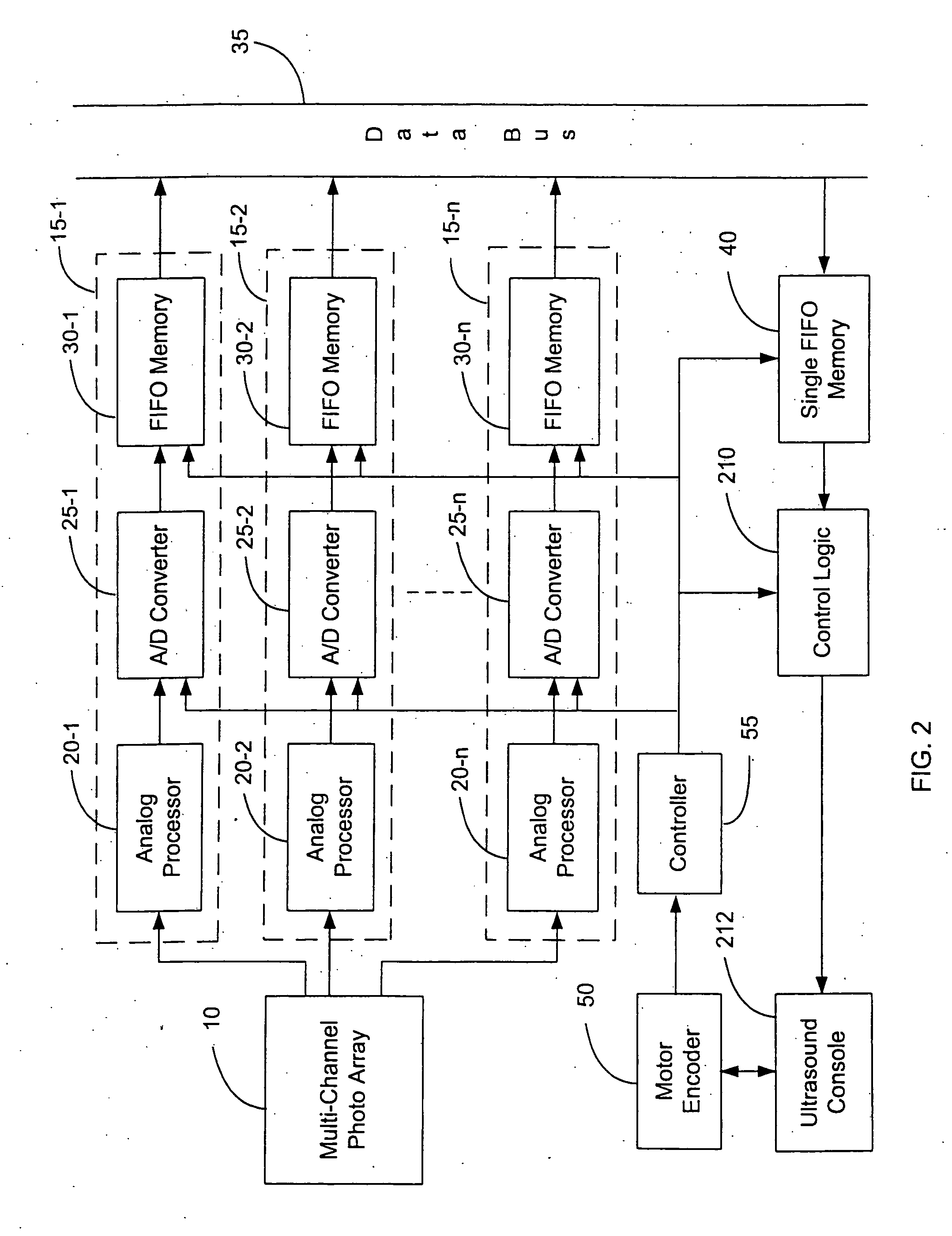
[0039] The electronics interface includes a plurality of channel processors 15-1 to 15-n, where each channel processor 15-1 to 15-n is coupled to one of the parallel channel outputs of the photo array 10. Each channel processor 15-n includes an analog processor 20-n, an A / D converter...


PUM

PropertyMeasurementUnit
time lengthaaaaaaaaaa
data acquisition timeaaaaaaaaaa
path lengthsaaaaaaaaaa

Abstract

An improved Optical Coherence Domain Reflectometry (OCDR) system is provided. One embodiment of this OCDR system outputs a detector signal carrying image depth information on multiple modulation frequencies, where each modulation frequency corresponds to a different image depth. The image depth information from the detector signal may be resolved by tuning to the desired modulation frequency. Another system for imaging body tissue uses multiple frequency modulators such that the light beam does not travel from an optical fiber to free space.

Description

CROSS REFERENCE TO RELATED APPLICATIONS [0001] This application is a divisional of co-pending application Ser. No. 10 / 690,948, filed Oct. 21, 2003, which is a divisional of U.S. Pat. No. 6,728,571, filed Jul. 16, 2001, and all patents and patent applications of which are expressly incorporated herein by reference for all purposes.FIELD OF THE INVENTION [0002] The invention relates generally to a method and system for making optical measurements, and in particular, to a method and system for making optical measurements for a catheter-based imaging system such as Optical Coherence Domain Reflectometry (OCDR). BACKGROUND OF THE INVENTION [0003] Ultrasound medical imaging is often used to produce images of blood vessels and surrounding tissue. To image a blood vessel and surrounding tissue, an Intravascular Ultrasound (IVUS) catheter is typically used. The IVUS catheter comprises an elongated member and an ultrasound transducer located at a distal end of the elongated member. The elonga...

Claims


Application Information

Patent Timeline
Patent Type & Authority Applications(United States)
IPC IPC(8): A61B6/00G01N21/17A61B5/00G01B9/02
CPCA61B5/0066A61B5/6852G01B9/02091G01B9/02002G01B9/02028
Inventor BARBATO, LOUIS J.
Owner SCI MED LIFE SYST
Why Eureka
Try Eureka