
Griddle plate having a vacuum bonded cook surface

a technology of vacuum bonding and cook surface, which is applied in the field of commercial cooking griddles, can solve the problems achieve the effects of reducing the thermal recovery time of the griddle, increasing the thermal conductivity of the cook surface, and high thermal conductivity coefficien

Inactive Publication Date: 2006-05-25
CLAD METALS
View PDF59 Cites 24 Cited by
  • Summary
  • Abstract
  • Description
  • Claims
  • Application Information

AI Technical Summary

Benefits of technology

[0008] Briefly stated, the present invention is directed to a composite griddle plate comprising a core consisting of a metal having a high coefficient of thermal conductivity such as copper or aluminum. The core plate is faced at least with an upper sheet of a metal such as stainless steel or titanium which defines the cook surface of the griddle plate. The interface between the core plate and upper sheet is under the reduced pressure of a vacuum so as to cause intimate contact between the core and cook surface which increases the thermal conductivity to the cook surface and, thus, reduces the thermal recovery time of the griddle.
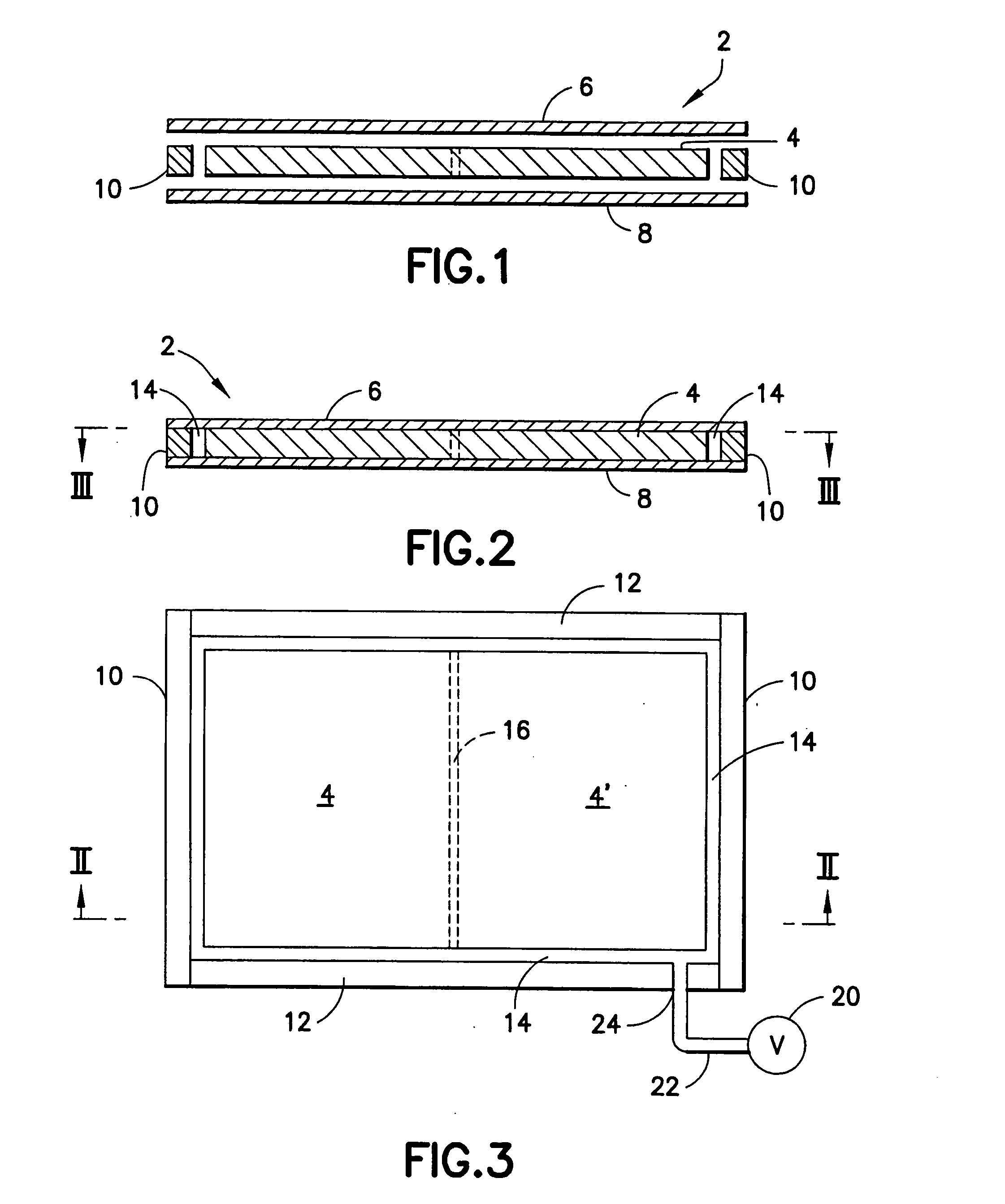
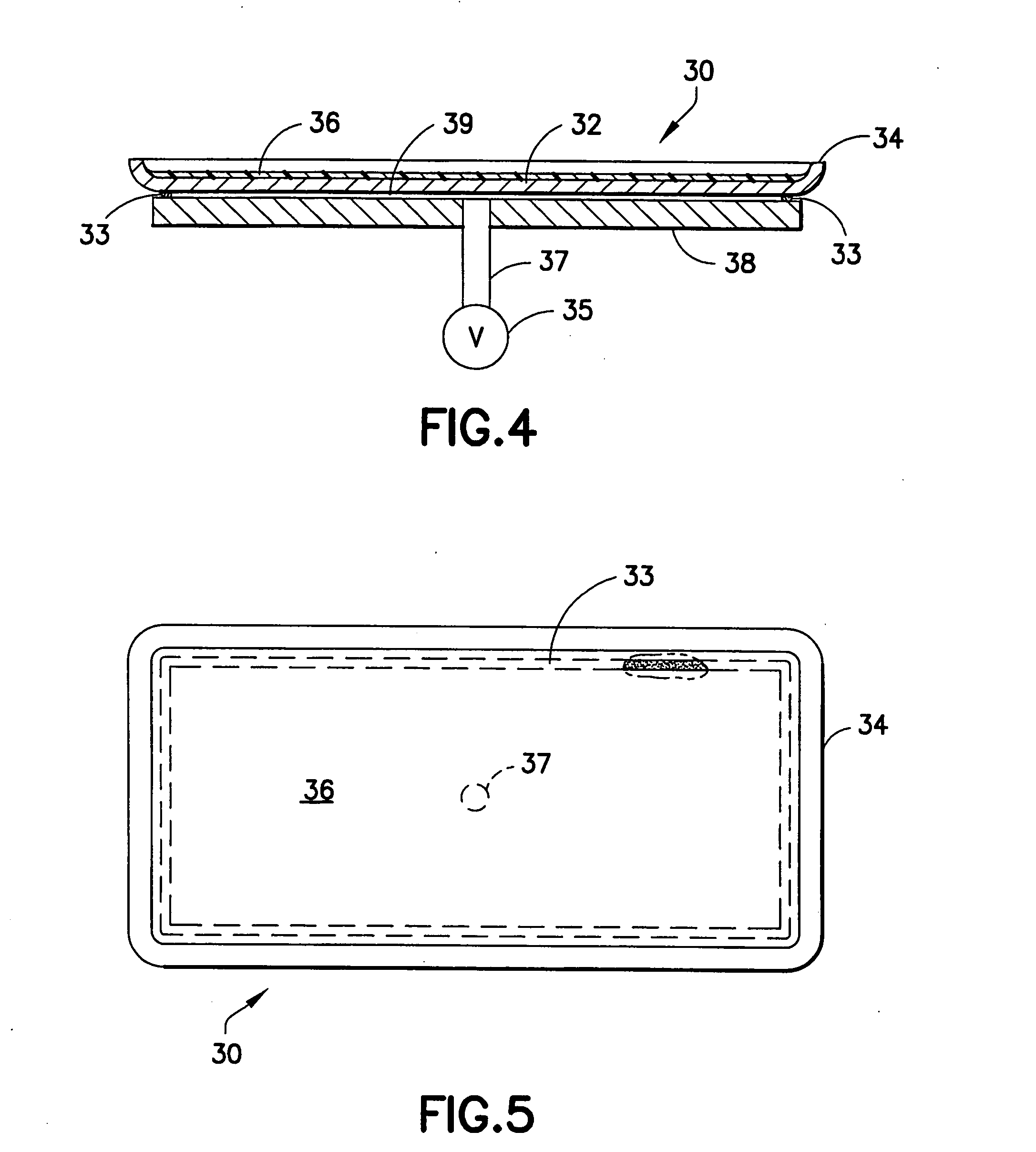
[0009] Various additional presently preferred embodiments of the invention are disclosed herein. For example, the griddle plate of one such embodiment comprises a high heat conductivity core of copper or aluminum having upper and lower sheets of stainless steel in intimate contact with the core. The entire perimeter of the griddle plate is sealed as by welding and the interior is under a permanently sealed vacuum. Another such presently preferred embodiment utilizes an upper sheet of stainless steel or other metal having a non-stick coating applied thereto. The upper sheet is removably secured to the heat conductive core plate under vacuum utilizing a high temperature gasket or adhesive sealant to maintain the vacuum. The upper sheet may be mechanically secured by bolts or the construction may be placed under a constant vacuum using a vacuum pump. When the non-stick surface ages and / or otherwise loses its non-stick properties, such as with a PTFE-type non-stick coating, the upper sheet can be easily replaced with a freshly non-stick coated upper sheet and the vacuum reestablished.

Problems solved by technology

The interface between the core plate and upper sheet is under the reduced pressure of a vacuum so as to cause intimate contact between the core and cook surface which increases the thermal conductivity to the cook surface and, thus, reduces the thermal recovery time of the griddle.

Method used


Image

  • Griddle plate having a vacuum bonded cook surface
  • Griddle plate having a vacuum bonded cook surface
  • Griddle plate having a vacuum bonded cook surface

Examples


Embodiment Construction

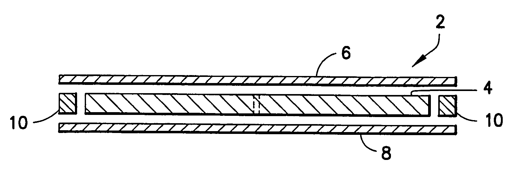
[0024] One presently preferred embodiment of the present invention is depicted in FIGS. 1-3 showing the composite griddle plate 2 comprising a core plate 4 having an upper sheet or cook surface 6 and a lower sheet 8. The core plate 4 is a metal having a high coefficient of thermal conductivity such as copper or aluminum. Of the two materials, copper is preferred from the standpoint of thermal conductivity, while aluminum is attractive from a weight standpoint in that aluminum is much lighter than copper in an equivalent thickness while having only a slightly lower coefficient of thermal conductivity. The sheets 6 and 8 in a preferred embodiment are both selected from stainless steel such as Type 304 stainless. However, they need not be of the same type. For example, the upper sheet may be of 304 stainless while the bottom sheet 8 can be a ferromagnetic material such as a carbon steel or a 400 grade ferritic stainless steel for induction cooking purposes. Bottom sheet 8 could also be...


PUM

PropertyMeasurementUnit
Curie temperatureaaaaaaaaaa
angleaaaaaaaaaa
thickaaaaaaaaaa

Abstract

A composite griddle plate comprising a first sheet of metal defining a cook surface and a core plate of a metal having a relatively high coefficient of heat conductivity wherein the first sheet remains in intimate contact with an upper surface of the core plate with the aid of a vacuum.

Description

CROSS-REFERENCE TO RELATED APPLICATION [0001] This application claims the benefit of U.S. Provisional Application No. 60 / 616,801 filed Oct. 7, 2004, and is hereby incorporated by reference in its entirety.BACKGROUND OF THE INVENTION [0002] 1. Field of the Invention [0003] The present invention relates generally to commercial cooking griddles and, more particularly, to a composite cooking griddle having a thin cook surface layer, preferably of stainless steel, that intimately contacts a thicker heat conductive core layer of copper or aluminum by means of a vacuum. [0004] 2. Description of Related Art [0005] In commercial cooking griddles there is a long-felt need to provide a cook surface with a fast thermal recovery time when cooking, for example, frozen hamburger patties. In conventional steel plate griddles, areas of the cook surface occupied by the frozen patties experience a decrease in temperature which requires a prolonged recovery time to reach a desired temperature for prope...

Claims


Application Information

Patent Timeline
Patent Type & Authority Applications(United States)
IPC IPC(8): A47J37/10
CPCA47J37/067B23K9/0026B23K26/206B23K26/28B23K26/3206B23K26/328B23K2203/04B23K2203/14B23K26/32B23K2103/05B23K2103/14B23K2103/16B23K2103/50
Inventor GROLL, WILLIAM A.
Owner CLAD METALS
Learn More