
Powder body melting burner

Active Publication Date: 2006-05-25
DAIDO STEEL CO LTD +1
View PDF8 Cites 9 Cited by
  • Summary
  • Abstract
  • Description
  • Claims
  • Application Information

AI Technical Summary

Benefits of technology

[0006] Moreover, in the conventional powder body melting burner 5, the length of the flames per fuel supplied into the furnace is long, so it is necessary to design the furnace to be high enough to keep the length of the flames inside the furnace. Thus, there is a drawback that the equipment cost will increase. Moreover, in the case where the height of the furnace is equal, if the length of the flames becomes long, the flames which have hit the molten material at the bottom of the furnace will reach the surrounding furnace wall, and thus there is a drawback that these high temperature flames will accelerate the wear out of the refractory materials of the furnace wall.
[0007] Under such circumstances, as the present inventor has investigated in various ways in search for the solutions for the above problem, it has been confirmed that the carry-over phenomenon described above is caused by the fact that because the powder body is supplied from the outside as to enclose the fuel to be injected from the center of the burner head, a part of the powder body that has been supplied to the relatively outside of the flames is spewed out without being accompanied by the flame flow. Accordingly, it has been found that if the powder body is supplied from the center of the burner head in place of the conventional method of supplying the powder body from the outside of the fuel, and if the fuel is supplied from a plurality of places in the outside of the powder body concerned, the above described carry-over phenomenon that the powder body escapes from flames can be suppressed drastically.
[0008] Moreover, because it can be conceived that the dominant cause why the length of flames becomes long is that the fuel is supplied from one place, the way of thinking has been changed like the above. Thus, it has been found that if the powder body is supplied from one place in the center of the burner head and if the fuel is supplied from a plurality of places that enclose the powder body concerned, the fuel would be burned in a dispersed state even with the same amount of fuel, and therefore the length of the overall flames can be shortened. MEANS FOR SOLVING THE PROBLEMS

Problems solved by technology

Thus, there is a drawback that the equipment cost will increase.
Moreover, in the case where the height of the furnace is equal, if the length of the flames becomes long, the flames which have hit the molten material at the bottom of the furnace will reach the surrounding furnace wall, and thus there is a drawback that these high temperature flames will accelerate the wear out of the refractory materials of the furnace wall.

Method used


Image

  • Powder body melting burner
  • Powder body melting burner
  • Powder body melting burner

Examples


Embodiment Construction

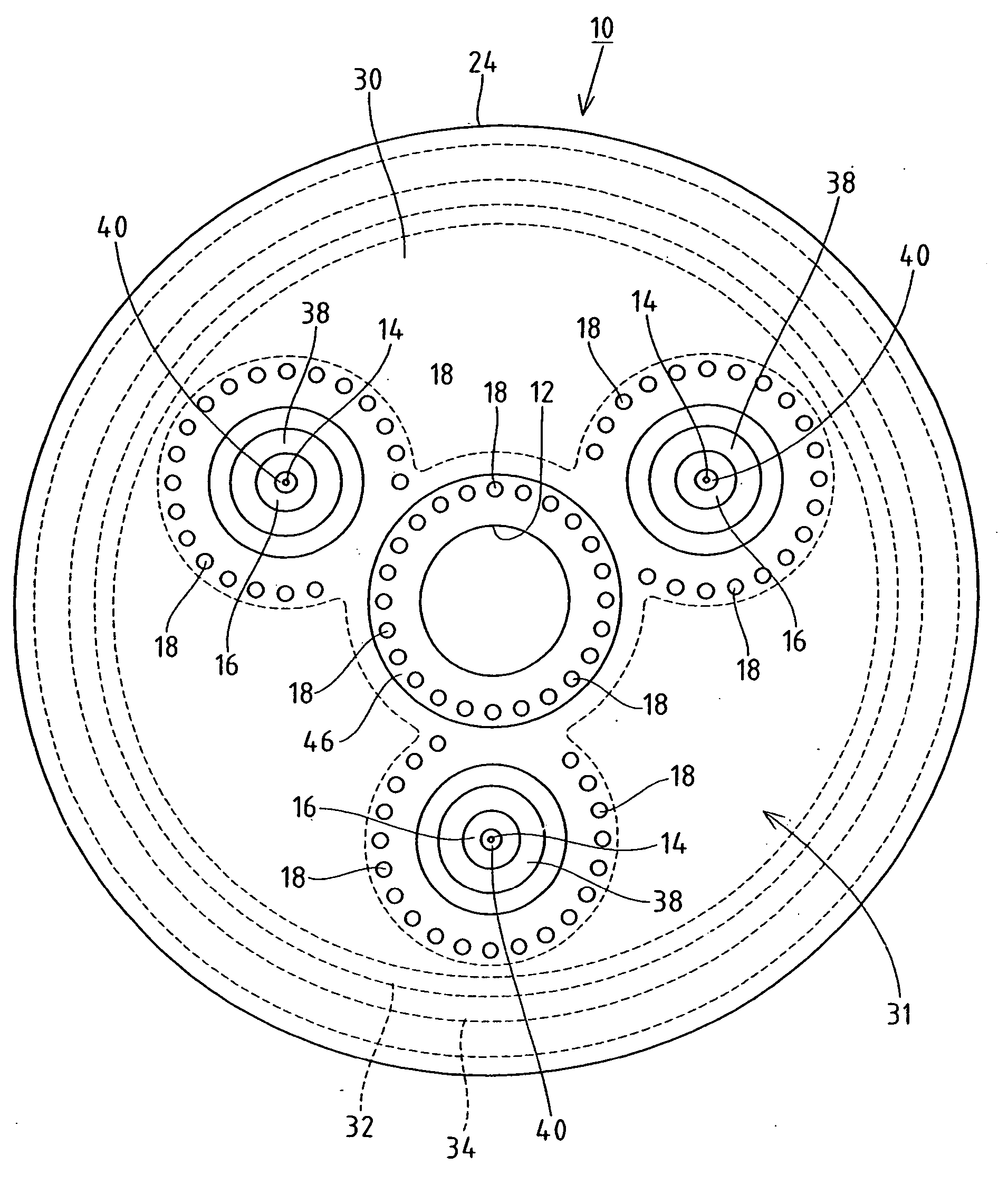
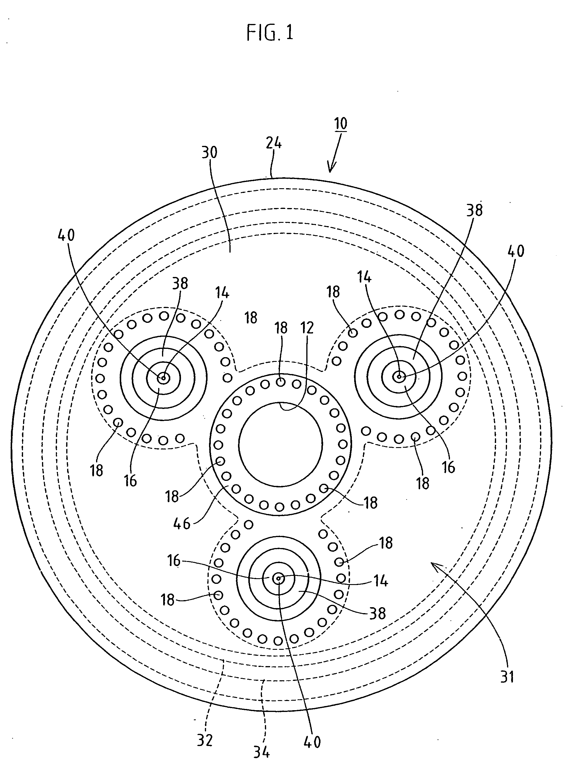
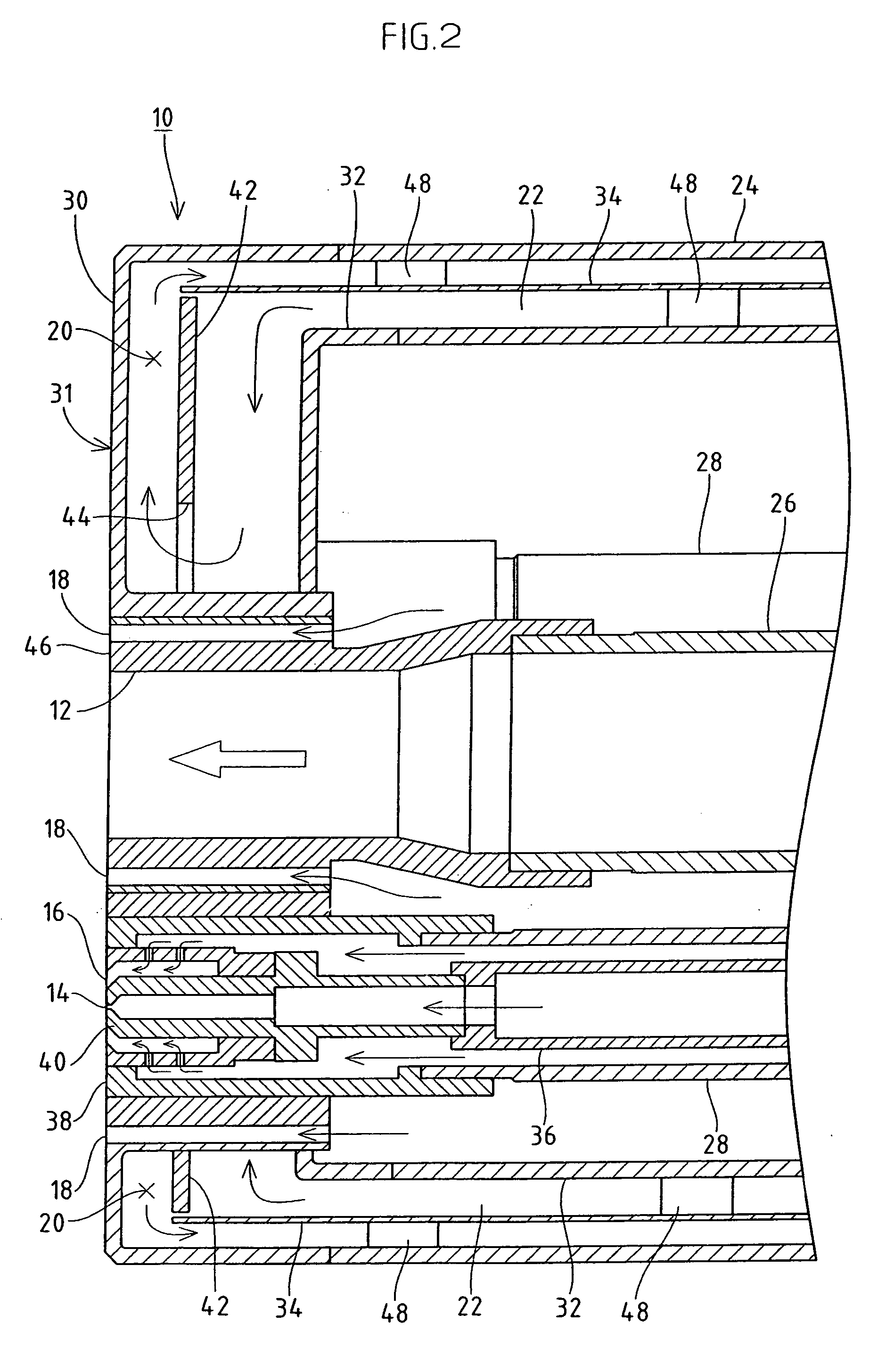
[0018] Next, a powder body melting burner according to the present invention will be described by way of a preferable embodiment with reference to the accompanying drawings. It should be noted that, in this embodiment, assuming heavy oils as the fuel, and moreover, water as the cooling medium used for the burner body and burner head, and moreover, an electric furnace dust, a reducing slag, a burned ash, or the like as the powder body or powder like perticulates. However, the scope of the present invention is not restricted thereto, as a matter of course.

[0019] Furthermore, the term “powder body” to be used in the present invention is not restricted to the so-called pure and simple powder-like powder body, but includes grain-like ones and granular ones, and further even a fluid body composed of the so-called collection of chip-like small pieces. Namely, one example of the powder body to be treated with the powder body melting burner according to the present invention includes an ele...


PUM

PropertyMeasurementUnit
Angleaaaaaaaaaa

Abstract

The object of the invention is to avoid a carry-over phenomenon that a part of powder body supplied into flames in a powder body melting burner escapes outside the flames is mixed, as unwelded, with an exhaust gas to be exhausted outside the furnace. A powder body melting burner (10) which injects a powder body, fuel, and oxygen into a furnace individually from a burner head (30) and melts the powder body in flames in which the fuel is burned under oxygen support, the powder body melting burner (10) includes a single powder body injection hole (12) provided in the center of the burner head (30); a plurality of fuel injection holes (14) disposed with a required central angle in the radial direction centering on the powder body injection hole (12); a single primary oxygen injection hole (16) provided concentrically with each of the fuel injection holes (14); and a plurality of secondary oxygen injection holes (18) arranged in large numbers with a predetermined interval so as to enclose each of the powder body injection holes (12) and the fuel injection holes (14), the plurality of secondary oxygen injection holes (18) forming a ring shape as a whole.

Description

TECHNICAL FIELD [0001] This invention relates to a powder body melting burner, and more particularly relates to a powder body melting burner used suitably for a melting treatment furnace in which powder particulates or the like made by crushing, for example, an electric furnace dust, a reduction slag, a burned ash and other plastic wastes are melted in high temperature flames and are recovered as a molten slag in a furnace, and to a powder body melting burner used suitably for a melting reduction furnace in which, for example, a powder-granular metal oxide, other metal sulfide or the like is melted in high temperature flames and at the same time the oxygen, sulfur, or the like are separated to recover as a molten metal in a furnace. PRIOR ART [0002] As the powder body melting burner, for example, there is one described in Japanese Unexamined Patent Publication No. 2000-103656. A powder body melting burner 5 disclosed in this publication, as shown in FIG. 3, includes a fuel supply ho...

Claims


Application Information

Patent Timeline
IPC IPC(8): C21C7/00F23C99/00F23D17/00F23D99/00F23J1/00F27D99/00
CPCC21B13/10C21C5/5217F23D17/007F23D99/003F23G5/12F23G2202/30F23G2209/28F23G2209/30F23L7/007F27D3/18F27D99/00Y02E20/322Y02E20/344F23D91/02Y02E20/32Y02E20/34Y02P10/20Y02P10/32
Inventor SATO WATARUWATANABE TOSHIKIOKAMOTO TETSUO
Owner DAIDO STEEL CO LTD
Features
  • Generate Ideas
  • Intellectual Property
  • Life Sciences
  • Materials
  • Tech Scout
  • Unparalleled Data Quality
  • Higher Quality Content
  • 60% Fewer Hallucinations
Learn More