
Surface acoustic wave device and electronic apparatus

Inactive Publication Date: 2006-05-25
SEIKO EPSON CORP
View PDF6 Cites 32 Cited by
  • Summary
  • Abstract
  • Description
  • Claims
  • Application Information

AI Technical Summary

Benefits of technology

[0009] An advantage of the invention is to provide a SAW device that has a good frequency temperature characteristic and easily provides a high-frequency application by using the upper limit mode of the stopband as the oscillation frequency of the SAW device.
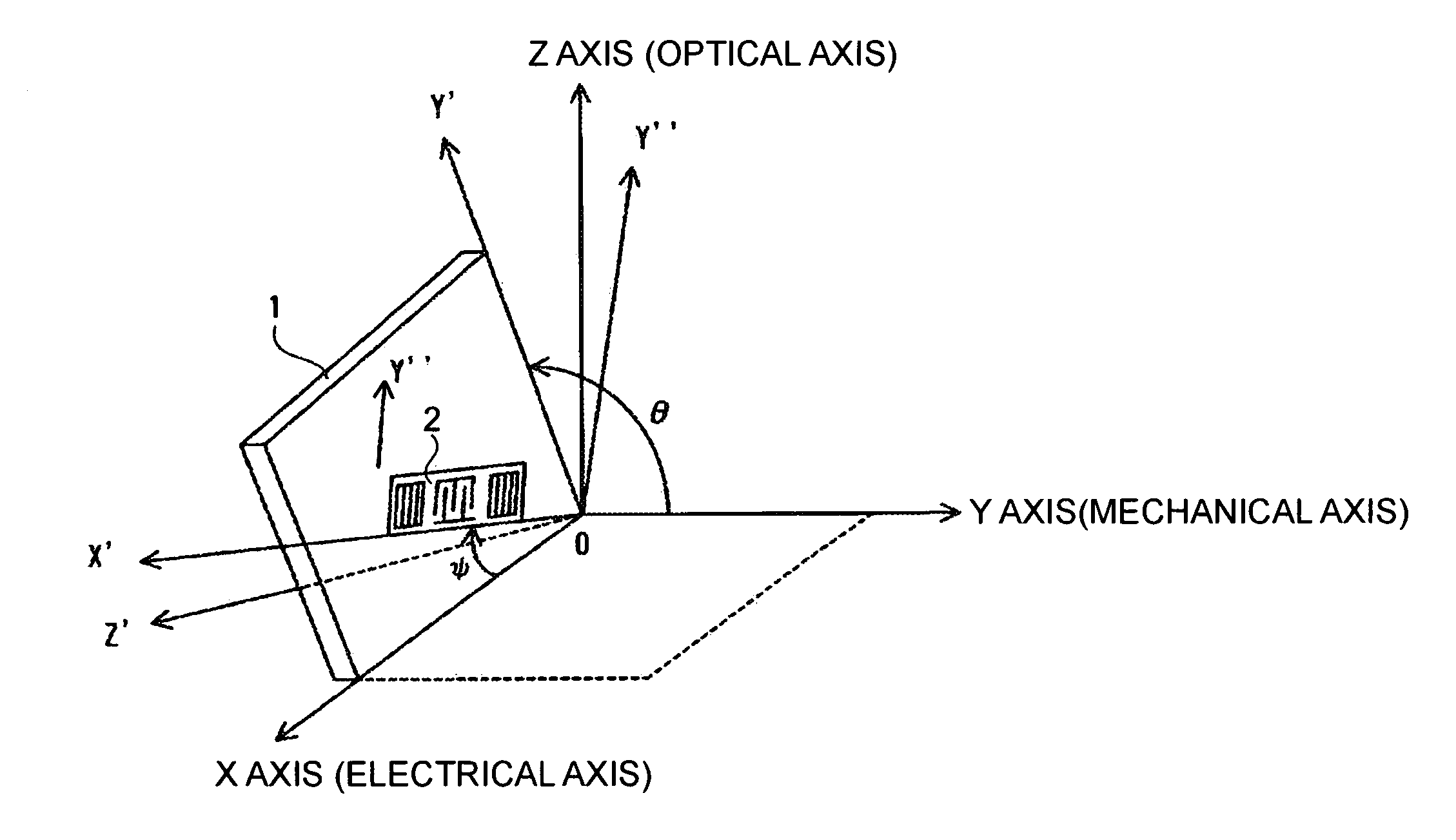
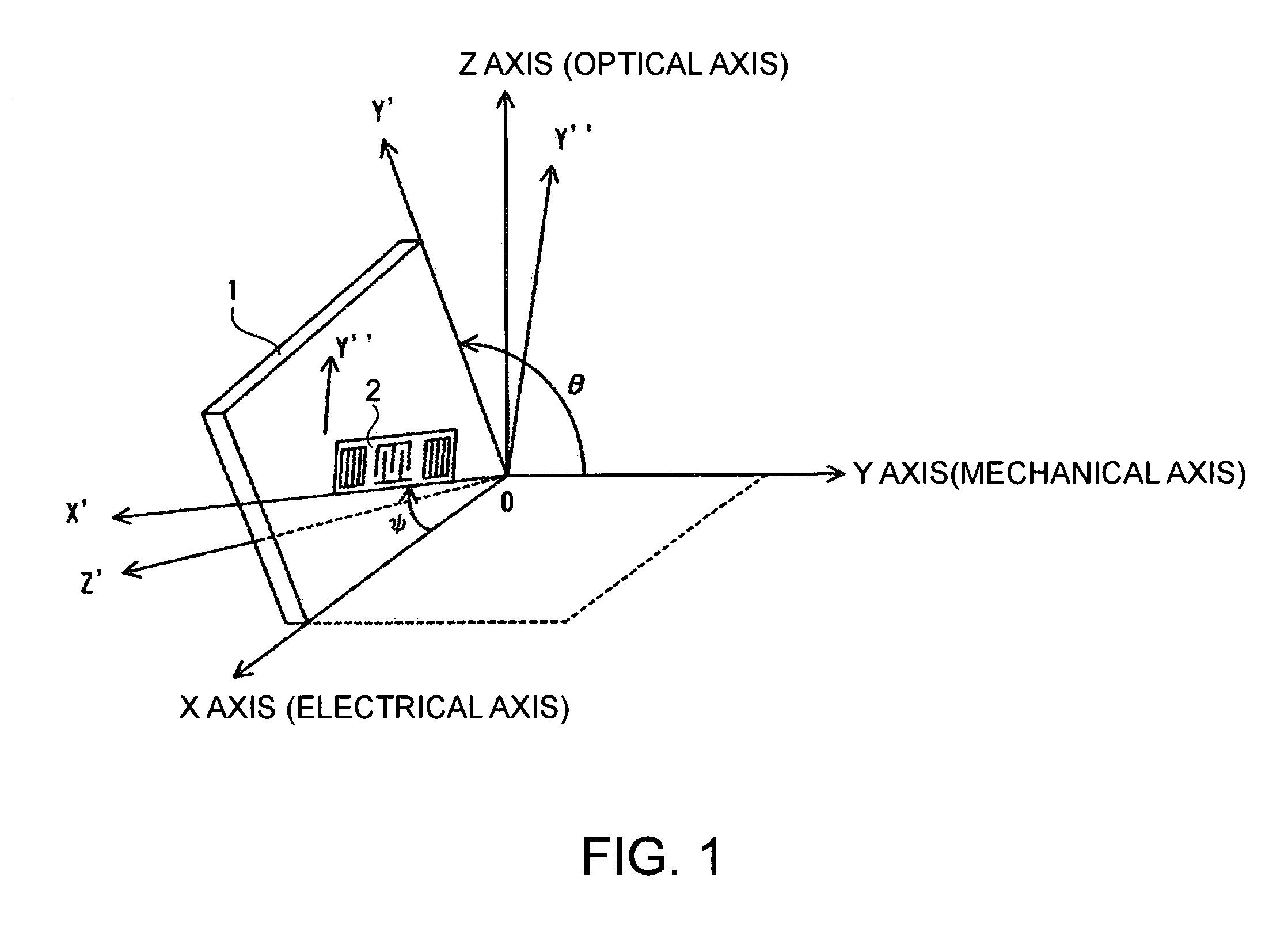
[0010] In a SAW device according to an aspect of the invention including at least an IDT electrode that excites a Rayleigh surface acoustic wave on a surface of a crystal substrate and giving excitation in the upper limit mode of a stopband of the surface acoustic wave, Euler angle representation (Φ, θ, Ψ) showing a cut angle and SAW propagation direction of the crystal substrate is set as (0°, 0°≦θ≦180°, 0°<|Ψ|<90°).
[0011] This structure can make the SAW propagation direction shift to a position remote from a quartz symmetry position in the quartz substrate, and can use the upper limit mode of the stopband as an oscillation frequency of surface acoustic waves. This structure thus facilitates a reduction in the size of the IDT electrode and easily provides high-frequency applications of the SAW device compared with using the lower limit mode of the stopband.
[0012] In the SAW device according to the invention, the IDT electrode may be a single IDT electrode.
[0013] This structure can use the upper limit mode without using a reflecting / inverting IDT electrode as the IDT electrode. Since it is sufficient to provide two electrode fingers with the single IDT electrode in one SAW wavelength, lowering of manufacturing yields can be reduced and high-frequency applications can be easily provided compared with using the reflecting / inverting IDT electrode, which requires three electrode fingers in one SAW wavelength.
[0014] In the SAW device according to the invention, Euler angle representation (ψ, θ, Ψ) showing a cut angle and SAW propagation direction of the crystal substrate may be set as (0°, 0°≦θ≦180°, 9°≦|Ψ|≦46°).

Problems solved by technology

However, a thicker IDT electrode is known to significantly lower the oscillation frequency.
To achieve both a thicker IDT electrode and a higher oscillation frequency, it is necessary to make the IDT electrode microscopic by further reducing its width, which may in turn lower manufacturing yields.
In other words, frequency variation with temperature changes increases, and thereby harming the temperature stability of the quartz substrate.
However, the single IDT electrode provided to the ST-cut quartz substrate is not capable of exciting surface acoustic waves in the upper limit mode.
Accordingly, the reflecting / inverting IDT electrode is not suitable for high-frequency applications, and its mass production may involve reduced yields.

Method used


Image

  • Surface acoustic wave device and electronic apparatus
  • Surface acoustic wave device and electronic apparatus
  • Surface acoustic wave device and electronic apparatus

Examples


first embodiment

[0034] One embodiment of the invention will now be described by taking a SAW resonator as an example of a SAW device. FIG. 3 is a schematic of this SAW resonator as a SAW device having a single IDT electrode. FIG. 3A is a schematic plan view showing the SAW resonator. FIG. 3B is a schematic sectional view along line A-A of FIG. 3A.

[0035] This SAW resonator 10 includes IDT electrodes 12 having electrode fingers 21, 22 on the surface of a quartz substrate 11, and reflectors 14, 15 provided on both sides thereof. The IDT electrodes 12 are arranged such that the electrode fingers 21, 22 are interdigitated with each other. The electrode fingers 21, 22 have a thickness H and a width d. A pitch P between the electrode fingers 21, 22 is fixed, and the space of the pitch is provided continuously. This structure includes two electrode fingers 21, 22 in one SAW wavelength λ. An IDT electrode having this structure of the IDT electrodes 12 is generally called a single IDT electrode. The IDT ele...

second embodiment

[0043] The cut angle and SAW propagation direction of the quartz substrate 11 provided with the SAW resonator shown in FIG. 3 can also be set within an Euler angle range of (0°, 0°−θ≦180°, 9°≦|Ψ|≦46°). As shown in FIG. 4, if the temperature ranges from −40 to 90 degrees Celsius, the frequency variation is about 127 ppm at the maximum. The second temperature coefficient of an ST-cut quartz substrate is generally represented by the formula: −3.4*10−8 {1 / (degrees C.)2}. If the temperature ranges from −40 to 90 degrees Celsius, the frequency variation is about 144 ppm.

[0044] Consequently, by setting the cut angle and SAW propagation direction of the quartz substrate 11 in the SAW device within the Euler angle range of (0°, 0°≦θ≦180°, 9°≦|Ψ|≦46°), the frequency variation can be lowered compared with using the ST-cut quartz substrate.

third embodiment

[0045] The cut angle and SAW propagation direction of the quartz substrate 11 provided with the SAW resonator shown in FIG. 3 can also be set within the Euler angle range of (0°, 95°≦θ≦155°, 33°≦|Ψ|≦46°). As shown in FIG. 4, if the temperature ranges from −40° to 90°, the frequency variation is about 59 ppm at the maximum. According to Temperature Stability of Surface Acoustic Wave Resonators on In-Plane Rotated 33°Y-Cut Quartz (JJAP, Vol. 42 (2003), pp. 3136-3138), the second temperature coefficient with an Euler angle representation of (0°, 123°, 43.4°) in the lower limit mode of the stopband is represented by the formula: −1.4*10−8{1 / (degrees C.)2}. If the temperature ranges from −40 to 90 degrees Celsius, the frequency variation is about 59 ppm.

[0046] Consequently, by setting the cut angle and SAW propagation direction of the quartz substrate 11 provided with the SAW resonator within the Euler angle range of (0°, 95°≦θ≦155°, 33°≦|Ψ|≦46°), the frequency variation can be lowered ...


PUM


Abstract

A surface acoustic wave device including at least an interdigital transducer electrode that excites a Rayleigh surface acoustic wave on a surface of a crystal substrate and giving excitation in an upper limit mode of a stopband of the surface acoustic wave, wherein Euler angle representation (ψ, θ, Ψ) showing a cut angle and surface acoustic wave propagation direction of the crystal substrate is set as (0°, 0°≦θ≦180°, 0°<|Ψ|<90°).

Description

BACKGROUND [0001] 1. Technical Field [0002] The present invention relates to a surface acoustic wave (SAW) device using an upper limit mode of the stopband of Rayleigh surface acoustic waves. [0003] 2. Related Art [0004] SAW devices, represented by SAW resonators and SAW filters, are widely used in the field of communications for their advantageous features in high-frequency and compact applications and in mass production. In particular, SAW devices using quartz substrates, represented by ST-cut quartz substrates, provide high accuracy with the high temperature stability of quartz. Further accurate SAW devices with higher stability for high-frequency and compact applications and for temperature changes have been required in recent years with the advance of mobile communications equipment, for example. [0005] Achieving SAW devices that can provide high-frequency applications and offer temperature stability involves conflicting factors to be resolved. Various efforts have been made to...

Claims


Application Information

Patent Timeline
IPC IPC(8): H03H9/17
CPCH03H9/02543H03H9/02551
Inventor KANNA, SHIGEO
Owner SEIKO EPSON CORP
Learn More