Pattern recognizing method and apparatus

a pattern recognition and pattern technology, applied in the field of pattern recognition methods and apparatuses, can solve the problems of large number of templates to be prepared, inability to detect patterns in the actual environment, and unrealistic computation requirements, so as to achieve fast and robust detection, low computing costs, and high detection accuracy

Inactive Publication Date: 2006-05-25
HITACHI LTD
View PDF1 Cites 50 Cited by
  • Summary
  • Abstract
  • Description
  • Claims
  • Application Information

AI Technical Summary

Benefits of technology

[0029] The present invention may realize the pattern recognizing method and apparatus with the higher detection accuracy by creating a large-scaled image database required for generating the statistic quality of the incremental signs and the feature vector for detecting the pattern generated from the statistic quality.
[0030] The pattern recognizing method and apparatus according to the present invention may realize a fast and rob

Problems solved by technology

As such, unlike the pattern detection in the well-conditioned environment, the pattern detection in the actual environment may suffer from the change of a size, the apparent change of a form and the variation of illumination at a time.
Hence, the use of the method based on the conventional template matching causes the number of templates to be prepared to be massive and thereby requires an unrealistic amount of computation.
However, this method is sensitive to the change of luminance and

Method used


Image

  • Pattern recognizing method and apparatus
  • Pattern recognizing method and apparatus
  • Pattern recognizing method and apparatus

Examples


first embodiment

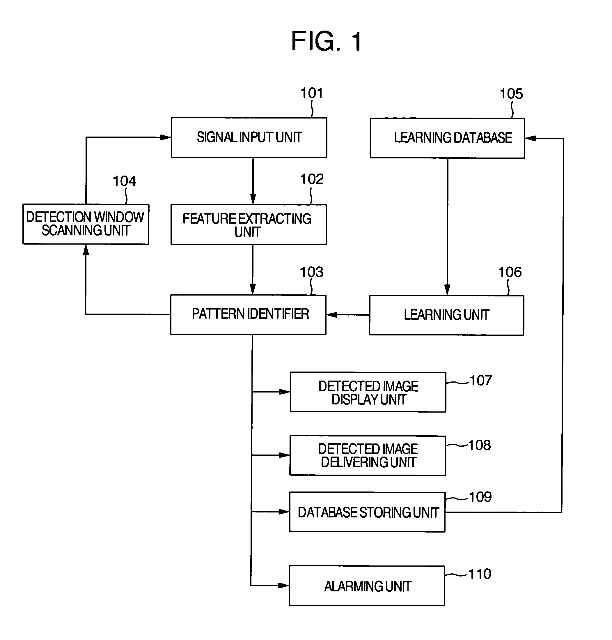
[0040]FIG. 1 is a block diagram showing the processing functions of a pattern recognizing apparatus according to an embodiment of the present invention. The pattern recognizing apparatus arranged as shown in FIG. 1 includes a signal input unit 101 being inputted with a signal sent from a camera, a feature extracting unit 102, a pattern identifier 103, a detection window scanning unit 104, a learning database 105, a learning unit 106, a detected image display unit 107, a detected image delivering unit 108, a database storing unit 109 for accumulatively storing detected images, and an alarming unit 110. Those functional blocks for executing the corresponding operations are configured with software on a system built in a computer provided with a CPU. The learning database 105 is configured in a storage unit such as a memory or a hard disk.

[0041] In this embodiment, the blocks of the signal input unit 101 to the detection window scanning unit 104 are intended to determine if an input s...


PUM


Abstract

A pattern recognizing method and apparatus are arranged to detect one or more objects with its own individuality belonging to the same category, such as a vehicle or a human's face, by using incremental signs in a manner to correspond with an apparent change caused by the posture variation of the object. For achieving the pattern detection corresponding with the apparent change caused by the posture variation of the object, the statistic quality of the incremental signs is extracted from a database having image data of the objects. The learning of a feature vector composed by using the quality makes it possible to design the most approximate identifier for detecting a pattern.

Description

BACKGROUND OF THE INVENTION [0001] The present invention relates to a method and an apparatus which are arranged to detect an object having a specific pattern from an image picked up by a camera. [0002] In a substrate inspecting technology dedicated for factory automation or an automatic address reading technology used in an automatic mail sorting machine, conventionally, a specific substrate or wiring pattern is searched for inspecting it or characters written on a mail are recognized. For these technologies has been used a matching method based on the normalized correlation of an image pattern or another matching method based on the feature quantity of a target object computed by extracting the edge information. These matching methods are basically executed on a two-dimensional pattern in the constantly illuminating condition, that is, in the well-conditioned environment. [0003] With recent advance of markets of a monitoring system or a security system, however, in the outdoor act...

Claims


Application Information

Patent Timeline
IPC IPC(8): G06K9/62G06K9/46
CPCG06K9/00228G06V40/161
Inventor KAZUI, MASATOKEUMI, SHIGEKIMIYAZOE, TATSUOTANIMOTO, JUNICHIMAEBAYASHI, KAZUYUKI
Owner HITACHI LTD
Why Eureka
Try Eureka