Method and apparatus for lapping gears

a gear and gear tooth technology, applied in the direction of gear teeth, gear manufacturing apparatus, manufacturing tools, etc., can solve the problems of affecting the quality of the gear teeth, the process used to make and the teeth of the ring gear and pinion gear may not conform to the design specifications

Inactive Publication Date: 2006-05-25
FORD GLOBAL TECH LLC
View PDF26 Cites 23 Cited by
  • Summary
  • Abstract
  • Description
  • Claims
  • Application Information

AI Technical Summary

Benefits of technology

[0012] In view of the above, the present invention is generally directed to a method for lapping the gears of a gear set as well as a gear lapping system. The gear set generally includes a first gear in meshed engagement with a second gear, each of the first and second gears having a plurality of gear teeth each with drive and coast flank surfaces. The method includes the steps of lapping the gear set by rotating the first gear in a first direction while the first gear is in mesh with the second gear. The method further includes sensing the vibrations occurring in the gear mesh during rotation and controlling the step of lapping based on the sensed vibrations. The gear lapping system includes an automated lapping machine that is adapted to lap the gear set including a ring gear and a pinion gear. The automated lapping machine is adapted to lap the gear set by rotating at least one of the ring and pinion gears while in mesh, in the presence of a lapping compound, and while translating the gear mesh back and forth across the gear flank surfaces for a plurality of cycles. A vibration sensor is operably coupled to the automated lapping machine and senses the amplitude of vibration and energy occurring in the gear mesh during each of the plurality of cycles. This sensor produces a vibration output signal that is proportional to the amplitude of the vibration energy. An automated controller is adapted to receive the vibration output signal as well as to calculate and transmit a control command signal to the automated lapping machine based on the amplitude of the vibration energy.

Problems solved by technology

The manufacturing processes employed to make the ring gear and pinion gear are complex processes comprising numerous metal-working, heat treatment and finishing processes.
Following the manufacturing process, either the ring gear, pinion gear, or both, may not conform to their design specifications.
Such non-conformance means that the teeth of these gears may not properly mesh with one another.
This non-conformance also produces vibration energy as the teeth of the gears are rotated while in mesh.
This vibration energy can produce various vibration waveforms, including audible noise.
However, this inspection technique adds time to the current manufacturing cycle, and utilizes a low speed (roughly 100 rpm) double flank roll at the mounting distance of the gear set.
In addition, the sensitivity of the measurement is such that it does not detect all nicks that are capable of diminishing the NVH performance of a gear set.
In some cases, due to teeth cutting errors, heat treatment distortion and other causes, the gear set must be scrapped.
While the typical single flank testing machines incorporating these vibration sensors provide useful information, they have a number of limitations.
This lapping / testing approach is undesirable in a high volume production environment because of the cost and time associated with transitioning the gear sets from the production lapping equipment to the testing equipment and back again if need be for additional lapping and / or testing.
While attempts have been made to correlate the amplitude of the time-based waveform and / or the frequency-based FFT output produced by testing with the NVH characteristics of the gear sets in the lapping environment or in their final applications, such efforts have had very limited success, because of the complexity of the factors to be considered, including the variability in the set-up of the gear set in manufacturing, final assembly and application, the broader range of rotational speeds in manufacturing and application versus testing, contact over a range of positions on the gear flank in manufacturing and application versus just one position during testing, as well as other factors.
However, all of these test methods have the disadvantage of being separate from the lapping process, and thus add cost and time to the production cycle.
Also, they provide relatively little quantitative information about the defects detected, the necessary corrective action required and whether a particular corrective action has produced the desired effect, absent retesting once the corrective measure has been taken.

Method used


Image

  • Method and apparatus for lapping gears
  • Method and apparatus for lapping gears
  • Method and apparatus for lapping gears

Examples


Embodiment Construction

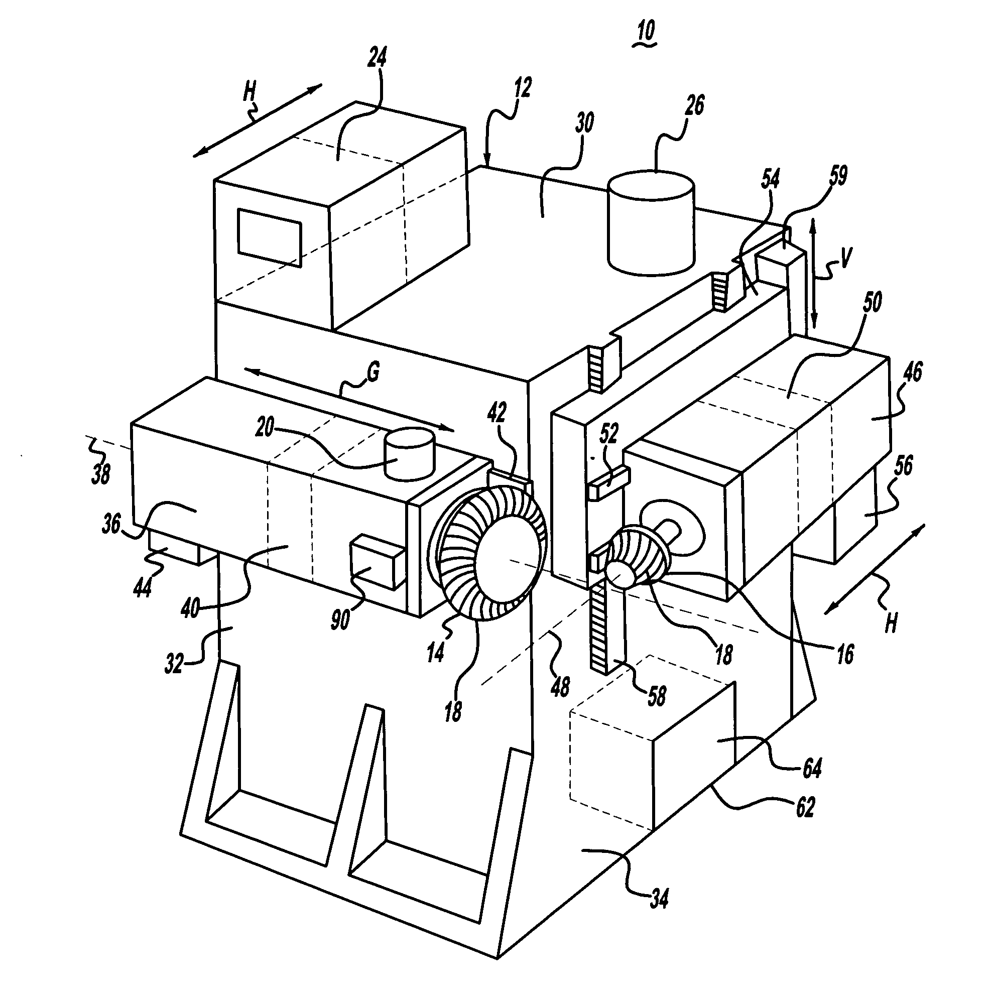
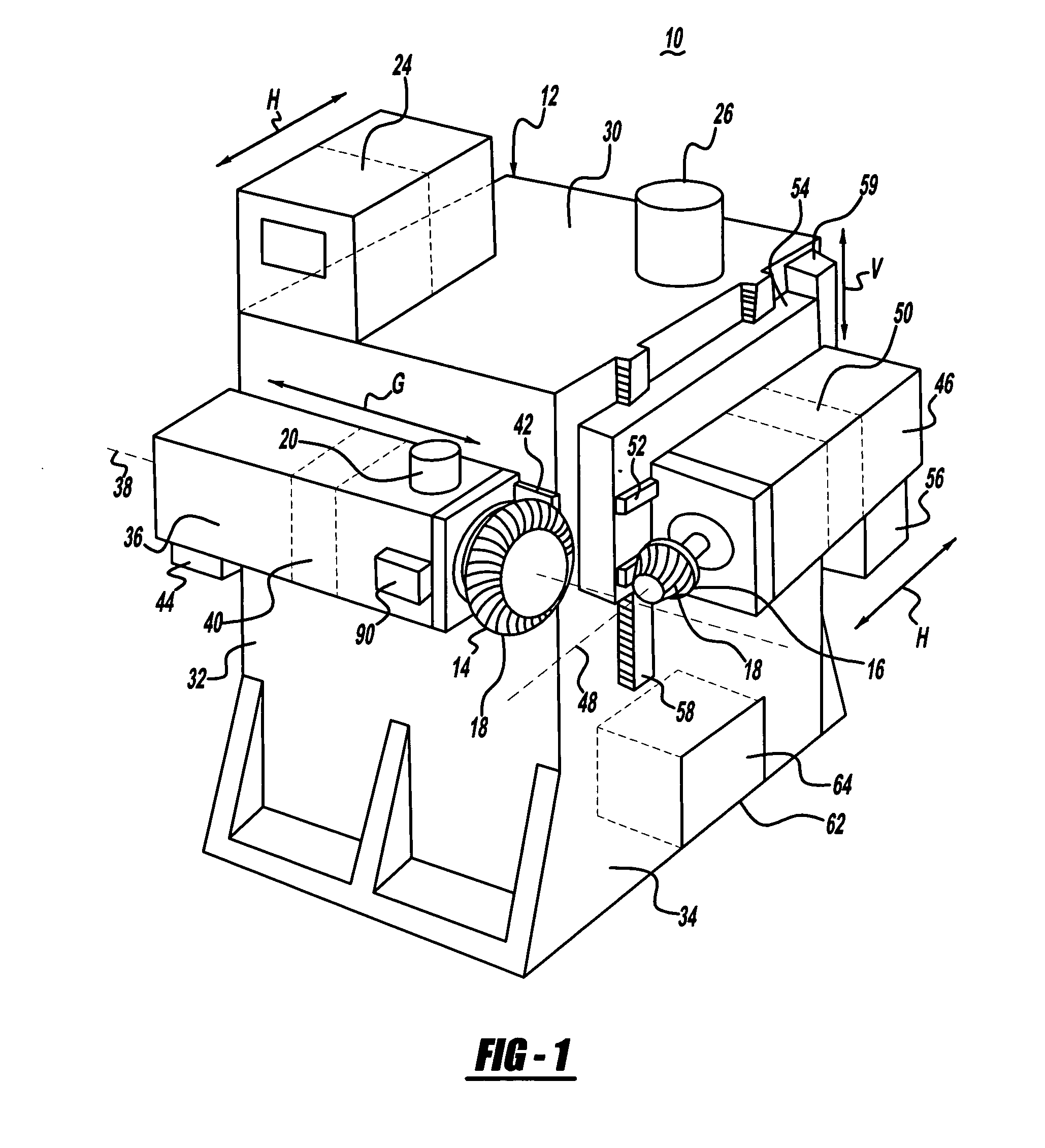
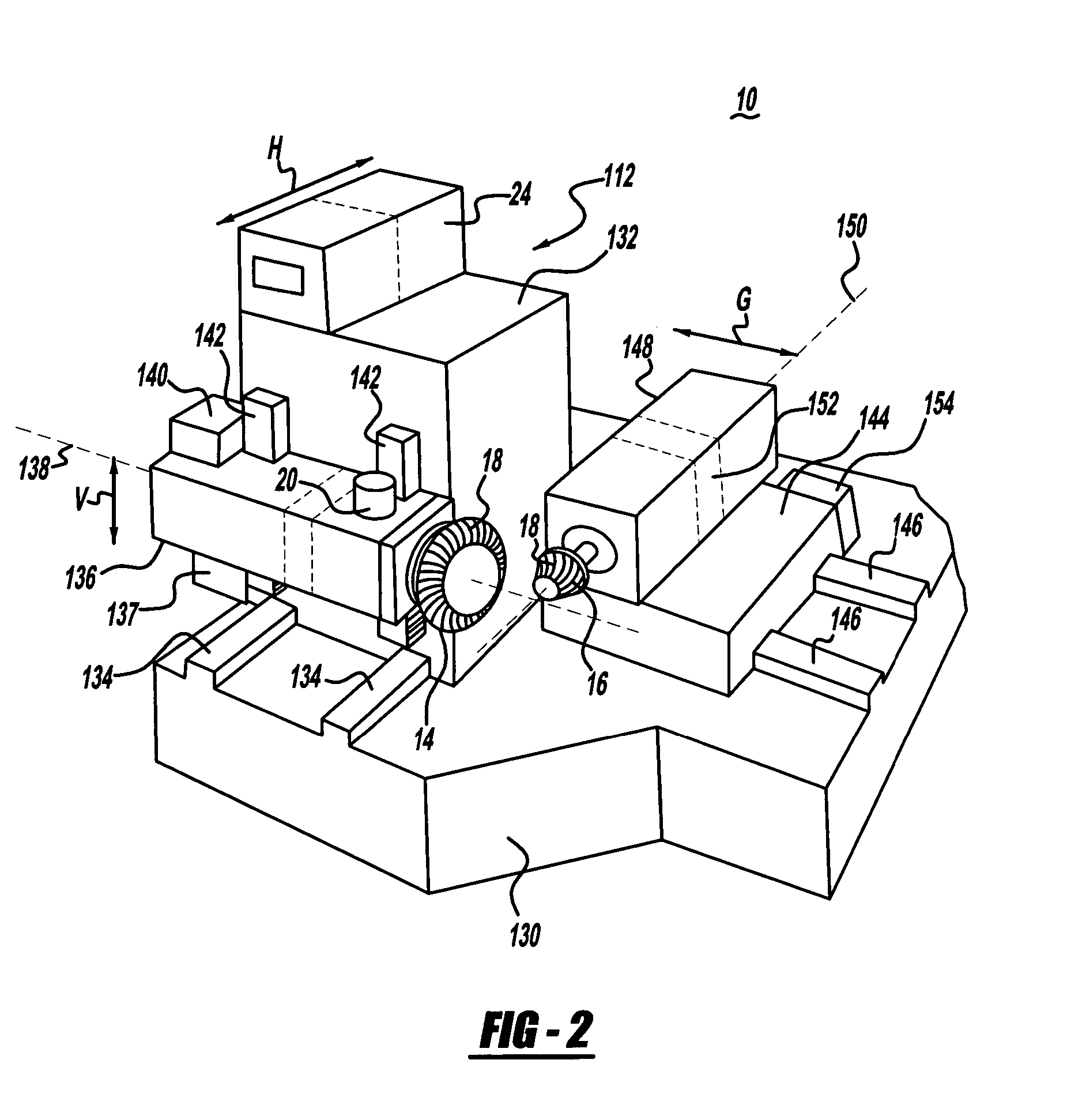
[0026]FIGS. 1-3 illustrate a gear lapping system 10 of the present invention. The system 10 includes an automated lapping machine 12 that is adapted to retain the mating gears 14,16 of a gear set 18 in mesh and exercise the gear set by rotation of the gears and the use of a pinion-cone motion (and possible gear cone motion and vertical and horizontal mounting offsets) between them and that is adapted to receive control inputs from an automated controller 24. The gear set 18 includes the first gear 14, having a plurality of first gear teeth each with drive and coast gear flank surfaces, and the second gear 16, having a plurality of second gear teeth each with drive and coast gear flank surfaces. During lapping the first and second gear teeth are in mesh and are indexed so that a starting position on the gear flank surfaces may be known (currently, the lapping cycle is based on time). The system 10 further includes a vibration sensor 20 that is adapted to provide a characteristic outp...


PUM

PropertyMeasurementUnit
data structureaaaaaaaaaa
speedaaaaaaaaaa
torqueaaaaaaaaaa

Abstract

A method for lapping the gears of a gear set as well as a gear lapping system. The gear set generally includes a first gear in meshed engagement with a second gear, each of the first and second gears having a plurality of gear teeth each with drive and coast flank surfaces. The method includes the steps of lapping the gear set by rotating the first gear in a first direction while the first gear is in mesh with the second gear. The method further includes sensing the vibrations occurring in the gear mesh during rotation and controlling the step of lapping based on the sensed vibrations. The gear lapping system includes an automated lapping machine that is adapted to lap the gear set including a ring gear and a pinion gear. The automated lapping machine is adapted to lap the gear set by rotating at least one of the ring and pinion gears while in mesh, in the presence of a lapping compound, and while translating the gear mesh back and forth across the gear flank surfaces for a plurality of cycles. A vibration sensor is operably coupled to the automated lapping machine and senses the amplitude of vibration and energy occurring in the gear mesh during each of the plurality of cycles. This sensor produces a vibration output signal that is proportional to the amplitude of the vibration energy. An automated controller is adapted to receive the vibration output signal as well as to calculate and transmit a control command signal to the automated lapping machine based on the amplitude of the vibration energy.

Description

FIELD OF THE INVENTION [0001] The present invention relates to a method of lapping the gears of gear sets. More particularly, it relates to a method and apparatus for detecting defects on the teeth of the gears and controlling a lapping machine based on the detected defects. BACKGROUND OF THE INVENTION [0002] Lapping is a well-established process for finishing the tooth surfaces of certain types of gear sets. It is particularly well suited for gear sets comprising a ring gear and associated pinion gear, such as such as bevel or hypoid gear sets. Such gear sets are frequently employed in automotive applications, such as driveline components, including the ring and pinion gear associated with a differential in an automotive vehicle [0003] In the lapping process, a ring gear and pinion gear are each typically mounted to rotatable spindles. These spindles are also frequently adapted such that either the ring gear, pinion gear or both may be translated back and forth with respect to the ...

Claims


Application Information

Patent Timeline
Patent Type & Authority Applications(United States)
IPC IPC(8): B24B51/00
CPCB23F17/001B23F19/02B23F23/1218
Inventor KOPP, GARY E.LOCKER, RICHARD W.MUZYK, BOGDAN F.SAID, MEDHAT
Owner FORD GLOBAL TECH LLC
Why Eureka
Try Eureka