

Combination oil ring
- Summary
- Abstract
- Description
- Claims
- Application Information
AI Technical Summary
Benefits of technology
Problems solved by technology
Method used
Image


Examples
first embodiment
A. First Embodiment
[0033] First, a combined oil ring of the first embodiment will be explained.
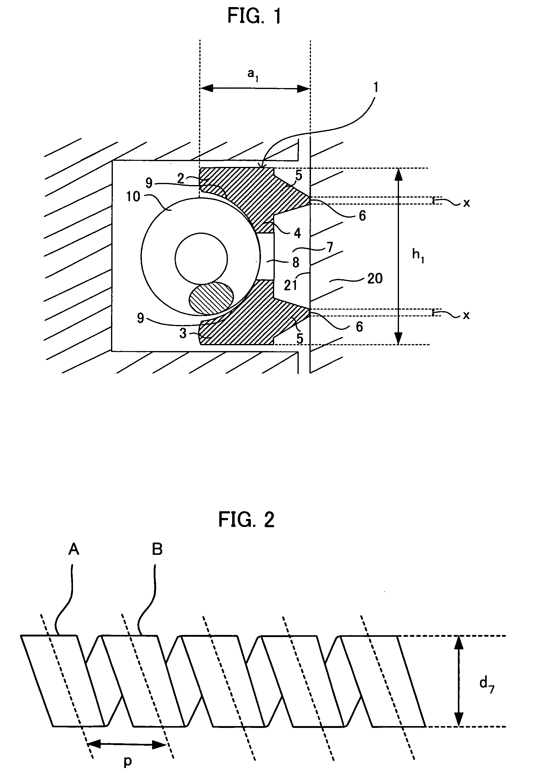
[0034] The combined oil ring of this embodiment comprises: an oil ring formed into cross-section substantially of an I-shape that two rails are connected at a columnar portion thereof; and a coil expander, which is placed in an inner peripheral groove formed on the inner side of a periphery of the columnar portion connecting the two rails of the oil ring, and which presses the oil ring radially outward, wherein the coil expander is formed of a shape memory alloy, and is formed of anomaly wire having rectangular cross sectional shape.
[0035] In this embodiment, the coil expander is formed of shape memory alloy, and uses anomaly wire having a rectangular cross sectional shape. Therefore, sufficient tension can be obtained without increasing the diameter of the coil of the coil expander. This is because of the following reason.
[0036]FIG. 4 is an explanatory view of a cross sectional shape o...
second embodiment
B. Second Embodiment
[0075] Next, a combined oil ring of a second embodiment of the present invention will be explained.
[0076] The combined oil ring of this embodiment comprises: an oil ring formed into cross-section substantially of an I-shape that two rails are connected at a columnar portion thereof; and a coil expander, which is placed in an inner peripheral groove formed on the inner side of a periphery of the columnar portion connecting the two rails of the oil ring, and which presses the oil ring radially outward, wherein a width of the oil ring in an axial direction is in a range of 0.3 mm to 3 mm, the coil expander is formed of a shape memory alloy, and the coil expander is treated such that if a temperature of the coil expander itself is higher than a martensitic transformation temperature of the shape memory alloy, the coil expander extends in its longitudinal direction.
[0077] In this embodiment, the combined oil ring is obtained by combining the thin oil ring in the abo...
example
[0116] Next, the present invention will be explained in more detail by way of an example. Ti—Ni-based alloy (50 to 51 atom % Ni alloy) was used as the shape memory alloy.
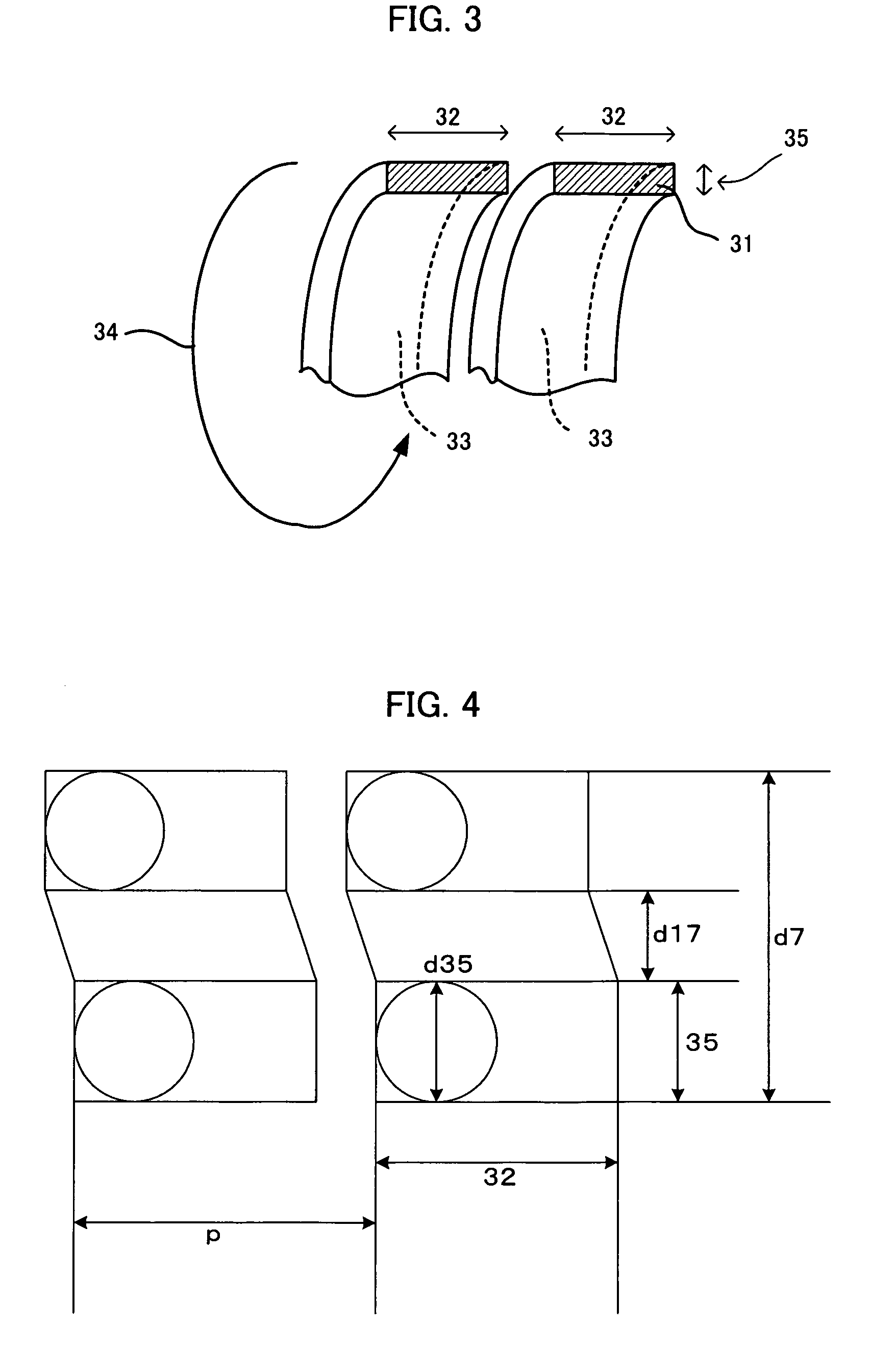
[0117] The variation of variable tension margin with respect to the ratio (aspect ratio) of the thickness and the width of the cross sectional shape of the anomaly wire of the coil expander was examined. FIG. 9 shows a result which is actually obtained by an experiment. In the experiment, the coil diameter (size d7 in FIG. 2) of the coil expander was changed in a range of 1.1 mm to 1.5 mm, the pitch (p in FIG. 2) was changed in a range of 0.7 mm to 1.4 mm, the thickness of the cross sectional shape of the anomaly wire (35 in FIG. 3) was changed in a range of 0.3 mm to 0.4 mm, and the width (32 in FIG. 3) was changed in a range of 0.45 mm to 1.00 mm. As spring distortions, the thickness of the cross sectional shape of the anomaly wire (35 in FIG. 3), the coil diameter of the coil expander (d7 in FIG. 2) and shrinkag...
PUM
 Abstract
Description
Claims
Application Information