Voltage regulator

a voltage regulator and voltage regulator technology, applied in the direction of electric variable regulation, process and machine control, instruments, etc., can solve the problem that the current power supply device b>15/b> cannot reliably protect the device itself or the load, and achieve the effect of simple circuit configuration and no longer starting tim

Inactive Publication Date: 2006-06-01
SONY CORP
View PDF3 Cites 31 Cited by
  • Summary
  • Abstract
  • Description
  • Claims
  • Application Information

AI Technical Summary

Benefits of technology

[0019] However, the voltage regulator 5 of the above-described configuration disconnects the gate of the output transistor Q2 from the current limiting circuit 11 at a starting time. Therefore, even when the load is short-circuited, or is an overload at the starting time, the current limiting circuit 11 does not function at all. Thus, when the load is short-circuited, or is an overload at the starting time, the voltage regulator 5 allows the output current to be an overcurrent exceeding an upper limit value, so that the output transistor Q2 and the load may generate heat.
[0024] Thus, according to the embodiment of the present invention, by changing the constant current type drooping characteristic for limiting the current value to the current limiting characteristic in the current limiting means when the enable signal for starting the operation of the control signal generating means is delayed by the delay time or less, the delay time corresponding to a certain time from a start of charging of the output capacitor to a completion of the charging of the output capacitor when the output capacitor can be normally charged to a specified capacity, it is possible to start lowering the current value of the output current from the first limit value to the second limit value at a time point at which completion of normal charging of the output capacitor is expected, that is, a time point at which completion of rising of the output voltage is expected, at the latest. The present invention can therefore prevent the output current limited to the first limit value, which is relatively high as a limit value, from continuing to flow after the time point at which completion of rising of the output voltage is expected, thus minimizing a time during which the output current having a current value limited to the first limit value continues flowing, and thereby prevent the output controlling means, a load and the like from generating heat.
[0025] According to the embodiment of the present invention, a voltage regulator that can prevent output controlling means, a load and the like from generating heat and protect the regulator itself and the load can be realized with a simple circuit configuration without lengthening a starting time.

Problems solved by technology

Therefore the direct-current power supply device 15 cannot reliably protect the device itself or the load L2.

Method used


Image

  • Voltage regulator
  • Voltage regulator
  • Voltage regulator

Examples


first embodiment

(1) First Embodiment

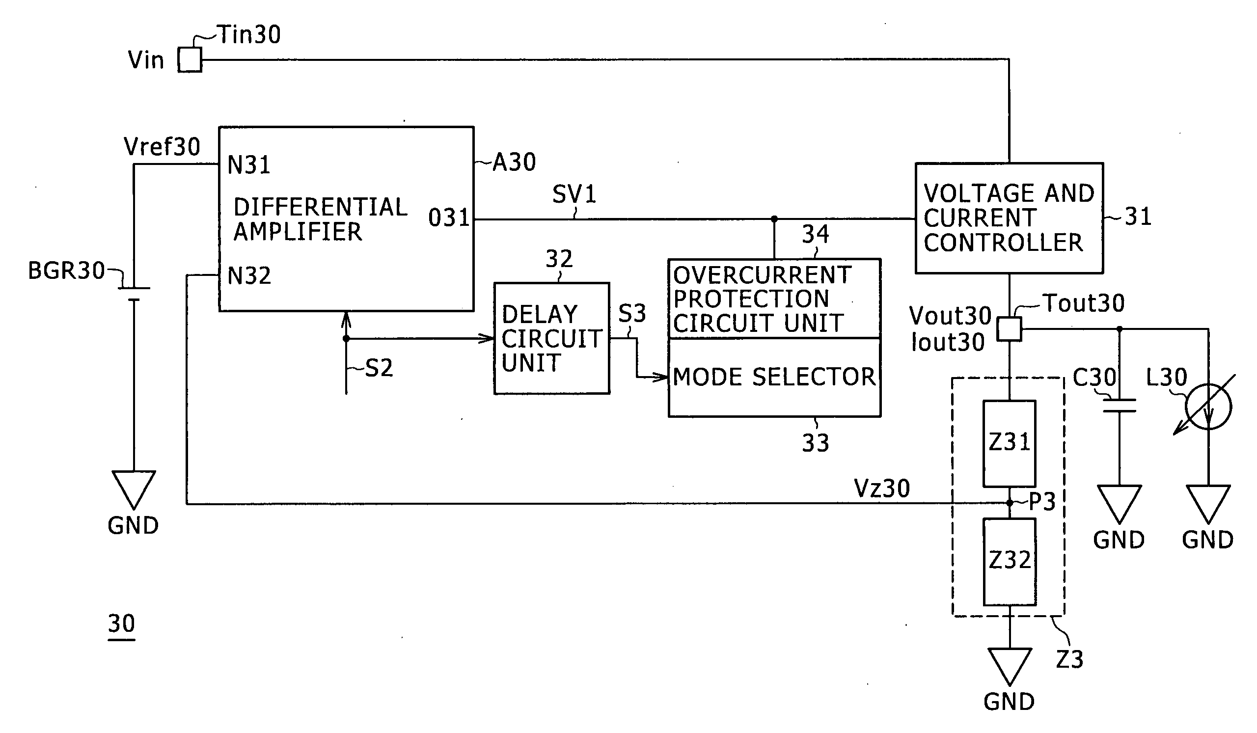
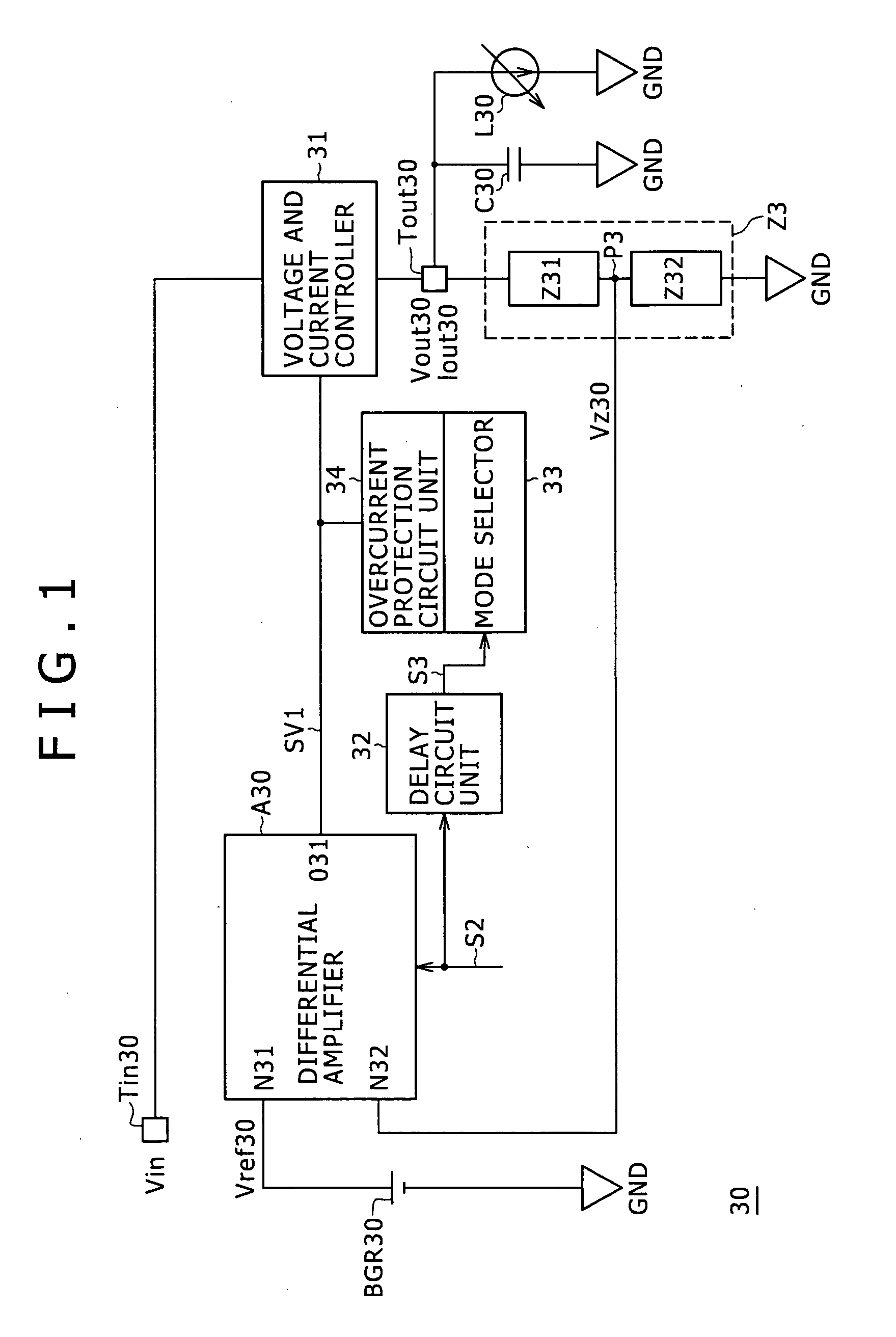
[0048] Reference numeral 30 in FIG. 1 denotes a voltage regulator as a whole according to a first embodiment. A first input terminal N31 of a differential amplifier A30 is connected to a reference voltage source BGR30, and an output terminal O31 of the differential amplifier A30 is connected to a voltage and current controller 31. The voltage and current controller 31 is also connected to an input terminal Tin30 supplied with a power supply voltage Vin from an input voltage source and an output terminal Tout30 of the voltage regulator 30. An output capacitor C30, a load L30, and a voltage divider Z3 for dividing an output voltage Vout30 occurring at the output terminal Tout30 are connected in parallel with each other between the output terminal Tout30 and a ground GND. The voltage divider Z3 is formed by a tenth voltage dividing resistance Z31 and an eleventh voltage dividing resistance Z32 connected between the output terminal Tout30 and the ground GND. An inter...

second embodiment

(2) Second Embodiment

[0119]FIG. 14, in which parts corresponding to those in FIG. 1 are identified by the same reference numerals, shows a voltage regulator 50 according to a second embodiment. An overcurrent protection circuit unit 51 is connected to an intermediate connection point between a differential amplifier A30 and a P-channel MOS type voltage and current controlling transistor Q30, for example, as a voltage and current controller. This overcurrent protection circuit unit 51 is also connected to an output terminal Tout30 via a third selector switch SW3. A fourth selector switch SW4 and a constant-voltage source VB is connected in series with each other between a ground GND and an intermediate connection point between the overcurrent protection circuit unit 51 and the third selector switch SW3. A delay circuit unit 32 is connected with the third selector switch SW3 via an inverter 52, and is directly connected with the fourth selector switch SW4.

[0120] In this case, at a ti...


PUM


Abstract

In a voltage regulator according to an embodiment of the present invention, a delay circuit delays an enable signal by a delay time or less, the delay time corresponding to a certain time from a start of charging of the output capacitor to a completion of the charging of the output capacitor, and sends the delayed enable signal as a delayed signal to a mode selector. An overcurrent protection circuit unit operates according to a constant current type drooping characteristic from a time point of input of the enable signal. The overcurrent protection circuit unit operates according to a current limiting characteristic that can lower an output current below an upper limit value after a time point of input of the delayed signal. Thereby the output current having the upper limit value is prevented from continuing to flow after a time point of completion of charging of the output capacitor at the latest. The voltage regulator according to the embodiment of the present invention can protect the regulator itself and a load without lengthening a starting time.

Description

CROSS REFERENCES TO RELATED APPLICATIONS [0001] The present invention contains subject matter related to Japanese Patent Application JP 2004-343012 filed with the Japanese Patent Office on Nov. 26, 2004, the entire contents of which being incorporated herein by reference. BACKGROUND OF THE INVENTION [0002] The present invention relates to a voltage regulator, and is suitable for application to a voltage regulator that is provided in a portable device such as a portable telephone or a PDA (Personal Digital Assistant), for example, and which has a protection function for preventing an output current from becoming an overcurrent (this function will hereinafter be referred to as an overcurrent protection function). [0003] As shown in FIG. 16, in a typical voltage regulator 1 having an overcurrent protection function, a first input terminal N11 of a differential amplifier A1 is connected to a reference voltage source BGR1, and an output terminal O11 of the differential amplifier A1 is co...

Claims


Application Information

Patent Timeline
Patent Type & Authority Applications(United States)
IPC IPC(8): G05F1/618G05F1/40
CPCG05F1/573
Inventor SUZUKI, TOSHIO
Owner SONY CORP
Why Eureka
Try Eureka