Radio frequency animal tracking system

a radio frequency identification and tracking system technology, applied in the direction of electrical signalling details, mechanical actuation of burglar alarms, instruments, etc., can solve the problems of inefficient and costly manufacturing and distribution process, inability to effectively query and retrieve identification numbers, and complex multi-layered and multi-step process of manufacture and distribution. achieve the effect of improving the real-time performance of the transponder

Inactive Publication Date: 2006-06-01
KALLINA +1
View PDF27 Cites 86 Cited by
  • Summary
  • Abstract
  • Description
  • Claims
  • Application Information

AI Technical Summary

Benefits of technology

[0008] The invention is directed to an improved RFID system, methods of using the system, and methods of making the system. In an embodiment, the system includes a transponder that can communicate over at least two different frequencies. Such an embodiment can provide improved real time performance of the transponder without losing backwards compatibility. In an embodiment, the system includes an improved apparatus and method that allows the end user to customize and program identification tags. The invention includes the tags including user provided data in print and / or in electronic form. In an embodiment, the system can provide an ear tag for use on livestock that exhibits advantageous performance in the field, shelter, and / or plant.

Problems solved by technology

Therefore, current RFID systems do not work well where fast data transmission is required, such as in certain real time tracking applications of fast moving objects.
More particularly, due to the inherent signal transmission delay associated with current RFID systems operated at 134.2 kHz, current systems cannot in certain circumstances effectively query and retrieve identification numbers, also commonly referred to as identification codes, from identification tags as the animals move rapidly past a particular point in space, such as when cattle move along a cattle chute commonly found at auctions or disassembly plants.
Unique challenges are associated with tracking livestock.
This complex multi-layered and multi-stepped process of manufacture and distribution is inefficient and costly.
In addition, current identification tags manufactured according to the above outlined processes are typically not customizable by the end users and generally include only a stored identification number.
This limitation may necessitate carrying a computer out in the field, which can be inconvenient and impractical.
In addition, once the livestock changes hands, the new livestock handler may not have access to the data that is associated with the identification number because the data is not transferred to the new handler.
Furthermore, current identification tags are not generally adapted to be used to measure physical parameters of the animals such as the animal's internal temperature, which can be helpful in determining if the animal is ill.

Method used


Image

  • Radio frequency animal tracking system
  • Radio frequency animal tracking system
  • Radio frequency animal tracking system

Examples


first embodiment

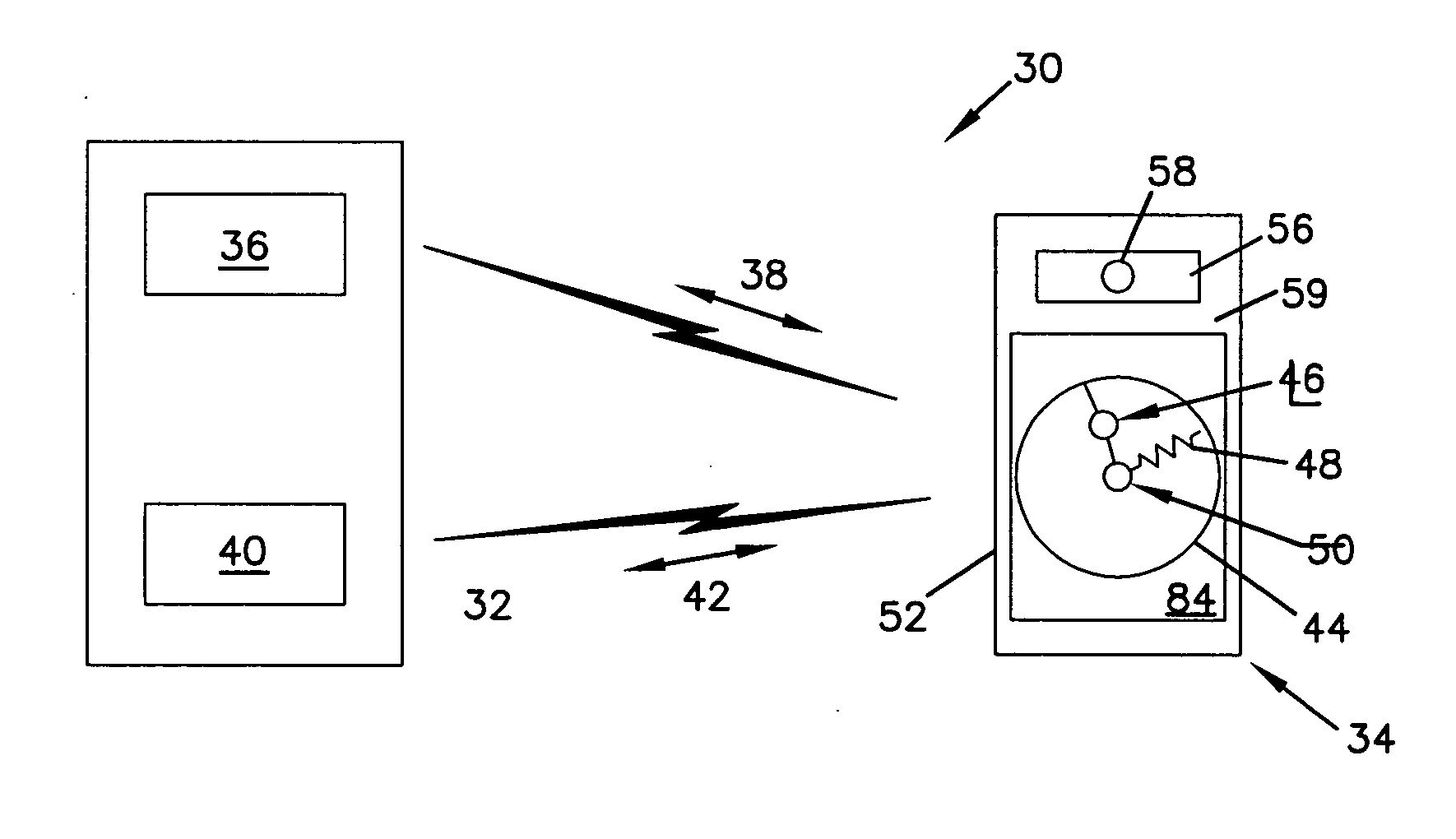
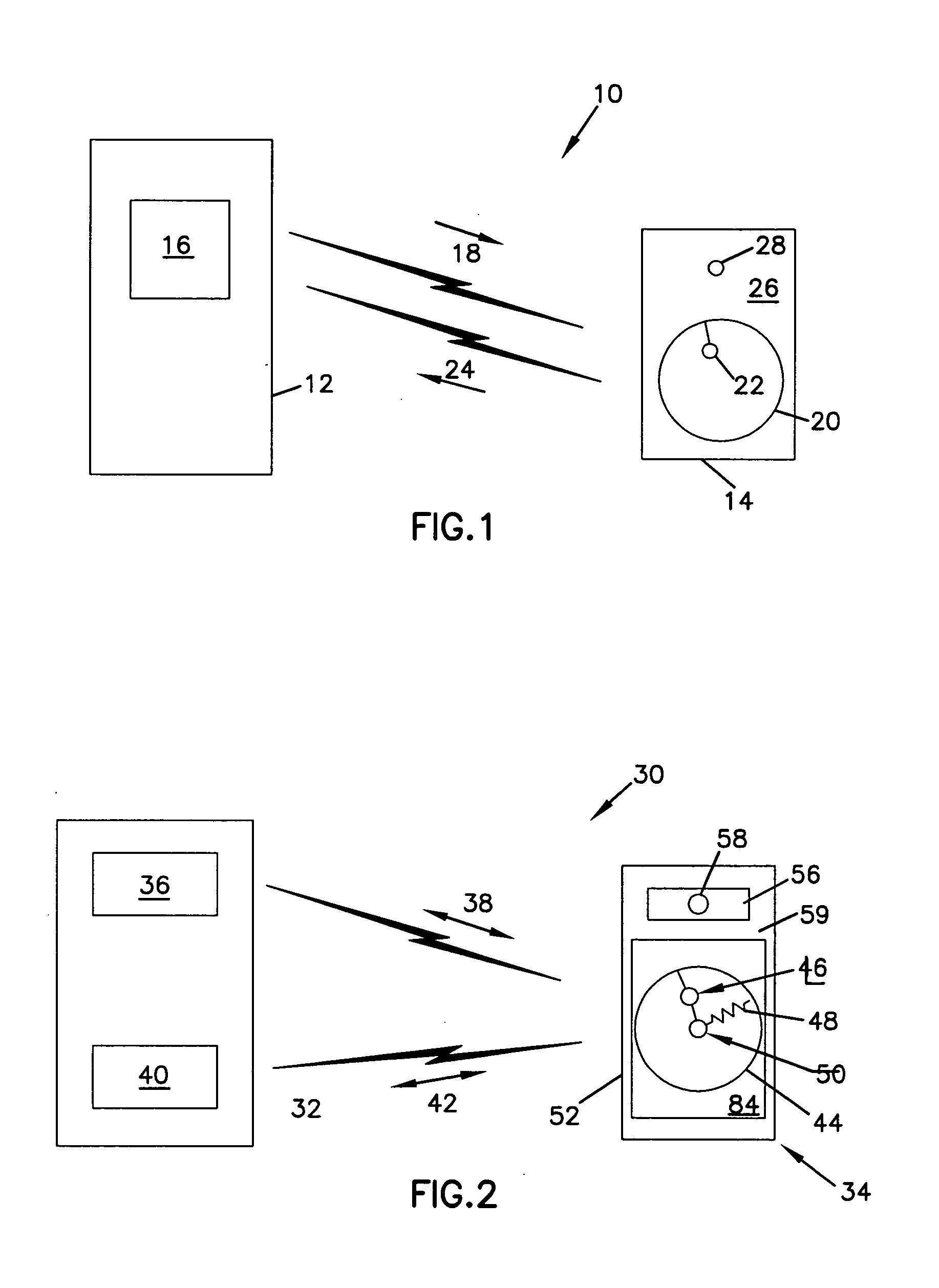
[0047] Referring to FIG. 2, an RFID system 30 according to the present invention is shown. In the depicted embodiment the RFID system 30 includes a base station 32 and a transponder 34. The base station 32 includes a first device 36 for transmitting and receiving signals at a first frequency 38 and a second device 40 for transmitting and receiving signals at a second frequency 42. In an embodiment, the first frequency 38 can be the standard frequency of 134.2 kHz and the second frequency 42 can be a higher frequency than the first frequency 38. The transponder 34 includes an antenna, e.g., a wire loop antenna 44, that is configured to receive and transmit on the first frequency 38. The depicted wire loop antenna 44 is made of metal and also functions as an inductor to generate an electrical current for powering a first semiconductor chip 46. The first semiconductor chip 46 can be programmed to retrieve a stored identification number and transmit that identification number back to th...

embodiment 130

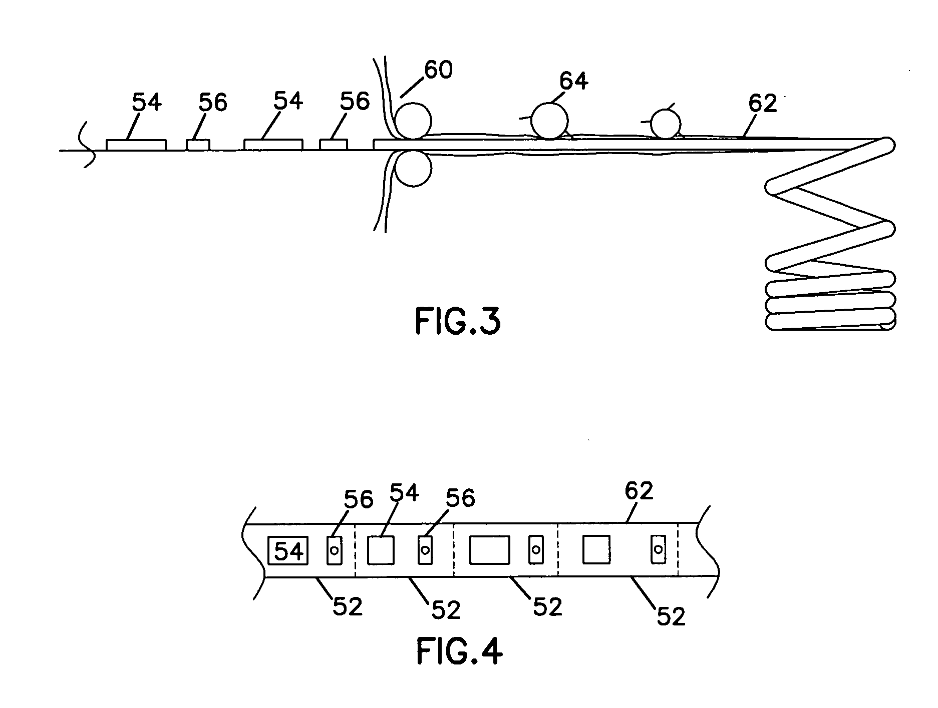
[0079] As shown in FIG. 10, a string of tags 122 formed on substrate 100 is maintained in a continuous strip 124, which may be fanfolded, rolled or otherwise packaged for sending to a producer, an auction lot, or other location within the animal production process. In an embodiment, tags 122 in strip 124 are inserted within a printing and encoding device 130 that may be positioned chute or corral side for ease of operation. Each of the tags 122 is pre-molded and encoded with a government issued identifier. Each of the tags 122 also includes area 128 for printing, embossing or otherwise marking with a local or management identifier. Area 128 allows a printing head 134 of chute side printer and encoder 130 to be used to apply a specific marking immediately prior to tag 122 being attached to the animal. While a novel printer / encoder embodiment 130 is described and shown herein, it is anticipated that tags 122 and strip 124 may be used with conventional printers currently in use for pri...


PUM


Abstract

The invention is directed to an improved RFID system. The system provides a transponder that can communicate over at least two different frequencies so that the real time performance of the transponder can be improved without losing backwards compatibility. The system provides an improved apparatus and method that allows the end user to customize and program identification tags. The system also provides an ear tag, which may be in button form, for use on livestock with superior durability and overall performance in the field.

Description

RELATED APPLICATIONS [0001] This application claims the benefit of U.S. Provisional Patent Application Ser. No. 60 / 629,013, filed Nov. 17, 2004; Ser. No. 60 / 706,645, filed Aug. 9, 2005; and Ser. No. 60 / 722,138, filed Sep. 30, 2005, all of which are hereby incorporated by reference for all they teach.FIELD OF THE INVENTION [0002] The invention relates to a radio frequency identification system and more particularly to a radio frequency identification system for tracking animals. BACKGROUND OF THE INVENTION [0003] Radio frequency identification (RFID) systems are well known. RFID systems are either active systems wherein the transponder includes its own power source or passive systems wherein the transponder receives its power from a base station. Since passive RFID systems do not require their own power source they are generally smaller, lighter, and cheaper to manufacture than active RFID systems. Consequently, passive systems are more commonly employed in RFID systems for the purpo...

Claims


Application Information

Patent Timeline
Patent Type & Authority Applications(United States)
IPC IPC(8): G08B1/08G08B13/14G08B23/00G08B5/22
CPCA01K11/004A01K11/006G08B29/16G06K19/07749G06K19/07758G06K19/07767
Inventor GEISSLER, RANDOLPH K.
Owner KALLINA
Why Eureka
Try Eureka