Multiple optical channels

a technology of optical channels and optical channels, applied in instruments, distance measurement, surveying and navigation, etc., can solve problems such as increasing the complexity of prisms, and achieve the effect of reducing the introduction of aberrations

Active Publication Date: 2006-06-01
TRIMBLE INC
View PDF6 Cites 17 Cited by
  • Summary
  • Abstract
  • Description
  • Claims
  • Application Information

AI Technical Summary

Benefits of technology

[0017] Tilting two plane parallel plates around axes that are perpendicular to e...

Problems solved by technology

Depending on the desirability of short telescope ...

Method used


Image

  • Multiple optical channels
  • Multiple optical channels
  • Multiple optical channels

Examples


second embodiment

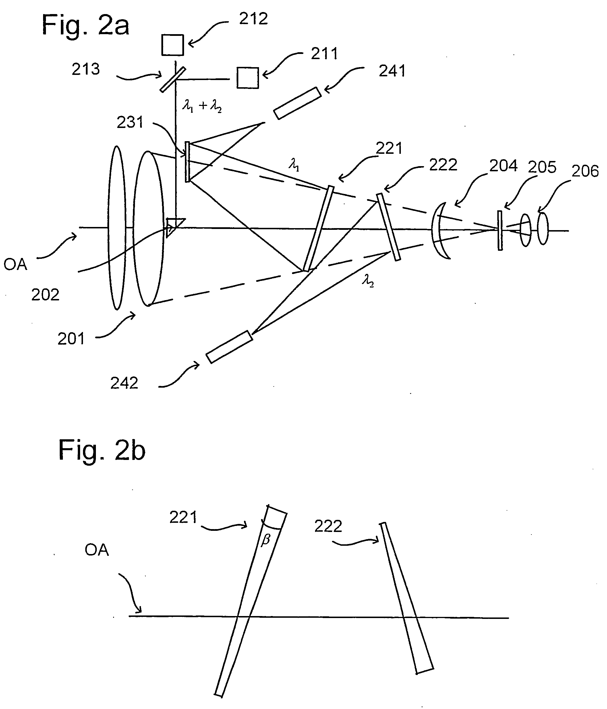
[0034] In FIG. 2a a second embodiment according to the invention is shown in which like numbers are used to indicate corresponding details. The lens system 201, the prism 202, the focusing lens 204, the reticle 205, the eyepiece 206 and the optical axis AO are similar to each other and serve essentially the same purposes.

[0035] In this second embodiment transmitter 211, transmitting light of the wavelength λ1, is arranged as in the first embodiment. The second transmitter 212 transmitting light of the wavelength λ2, is arranged in the same manner as transmitter 115 in the first embodiment, making one dichroic mirror superfluous.

first embodiment

[0036] The optical path for λ1 for the light reflected from the target will essentially be the same as in the first embodiment via the dichroic mirror 221 and mirror 231 towards the receiver 241. Further the tilt angle of the dichroic plates 221 and 222 have been changed such that the once reflected light of the wavelength λ2 is directed towards the receiver 242. This has been accomplished by resizing the distance between the plate 221 and / or by changing the tilt angles of the plates to allow the beam λ2 reflected in plate 222 to reach the receiver passing essentially adjacent to plate 221, i.e. plate 221 will not reach in to the reflected beam from plate 222. This figure also illustrates the capability to direct the beam to the detector without a second reflecting mirror.

[0037] The dichroic plates may exhibit a wedge form in order to compensate for optical aberrations in the visual channel. This is illustrated in FIG. 2b in which the two plates 221 and 222 are shown, and the optica...

third embodiment

[0038] In FIG. 3 a third embodiment according to the invention is shown in which like numbers are used to indicate corresponding details. In this embodiment the aberration compensation is accomplished by the compensating plate 307. The lens system 301, the prism 302, the focusing lens 304, the reticle 305, the eyepiece 306 and the optical axis AO are similar to each other and serve the same purposes.

[0039] In this third embodiment transmitter 311, transmitting light of the wavelength λ1 and the second transmitter 312 transmitting light of the wavelength λ2, are arranged in the same manner as in embodiment 1 using dichroic mirrors 313, 314 to bend the light towards the prism 302.

[0040] The optical path for λ1 for the light reflected from the target will essentially be the same as in the first embodiment via the dichroic mirror 321 and 331 towards the receiver 341. The beam λ2 has a beam path essentially as in FIG. 1 reflected in mirrors 322 and 332 to the receiver 342.

[0041] In thi...


PUM


Abstract

The invention relates to an electronic distance measuring apparatus for surveying, e.g. for measuring the distance from the apparatus to an object. The apparatus comprises: a) an objective lens (101), defining an optical axis (OA), b) at least two sources (111, 112) of structured light for transmitting beams (λ1, λ2) of separate wavelengths towards said object, said beams on reflection from said object received by the objective lens (101), (c) at least two receivers (141, 142) arranged outside a beam path (109) as defined by the objective lens (101), and adapted to receive said received beams (λ1, λ2) of structured light. Optical means comprising at least two dichroic surfaces (121a, 122a) are each arranged at a tilt angle (α1, α2) with respect to said axis (OA), said optical axis (OA) passing through said surfaces, at least one of said dichroic surfaces arranged on a plate (121, 122), said at least two dichroic surfaces (121a, 122a) adapted to reflect at least one of said received structured light beams (λ1, λ2), respectively, towards said receivers (141, 142).

Description

FIELD OF THE INVENTION [0001] The present invention generally relates to an automatic survey instrument comprising a source of structured light for transmitting a beam of said light towards said object, a receiver adapted to receive said reflected structured light beam when reflected from said object, said received light being co-axial with the transmitted light, an objective lens and a reticle with optical means positioned there-between, said objective lens and said reticle defining an optical axis. The invention more specifically relates to the arrangement for redirecting the reflected light in the receiver. BACKGROUND ART [0002] Automatic survey instruments of the present type comprise a telescope system where received light can be divide into separate channels for range-finding, tracking and viewing or manual aiming. The transmitter beam for the range-finder and for the tracker function are preferably coaxial to the receiver optics. [0003] The light reflected from the target obj...

Claims


Application Information

Patent Timeline
IPC IPC(8): G01C3/08G01C3/18G01C3/06G01S7/48G01S17/08
CPCG01C3/18G01C3/08
Inventor ANDERSSON, LEIFHERZMAN, MIKAELGRASSER, CHRISTIANRICHTER, ROLF
Owner TRIMBLE INC
Why Eureka
Try Eureka