Storage element and memory

a technology applied in the field of storage elements and memory, can solve the problems of reducing the thickness of the address wiring, unable to withstand the voltage of the barrier layer, and not being obtained, so as to reduce the power consumption of the whole memory, improve the efficiency of spin injection, and reduce the amount of electric current required

Active Publication Date: 2006-06-01
SONY CORP +1
View PDF4 Cites 48 Cited by
  • Summary
  • Abstract
  • Description
  • Claims
  • Application Information

AI Technical Summary

Benefits of technology

[0060] According to the above-mentioned present invention, it is possible to decrease the electric current amount required to record information by improving the spin injection efficiency.
[0061] As a consequence, it becomes possible to decrease power consumption of the whole of the memory.
[0062] Accordingly, it becomes possible to realize the memory with low power consumption that has never existed in the related art.
[0063] Also, according to the present invention, when recorded information is read, high output can be obtained and hence it becomes possible to read information easily.
[0064] As a result, in the memory including the storage element, the electric current applied to the storage element when information is read, for example, can be decreased, whereby it becomes possible to decrease power consumption required upon reading and the arrangement such as a circuit for detecting an output can be simplified.

Problems solved by technology

However, since the DRAM is a volatile memory whose stored information is lost when operating power is removed, a nonvolatile memory whose information may not be lost even when operating power is removed has been desired.
However, as the element constructing the MRAM is microminiaturized increasingly, the address wiring also is decreased in thickness so that an electric current of a sufficient magnitude may not flow through such thin address wiring.
In this case, it is inevitable that a withstand voltage of a barrier layer will be limited.
However, having manufactured a storage element having the structure described in the above-described cited patent reference 2 in actual practice and examined characteristics of this storage element, it is to be appreciated that satisfactory results could not be obtained theoretically so that satisfactory improvements of spin injection efficiency could not be recognized.

Method used


Image

  • Storage element and memory
  • Storage element and memory
  • Storage element and memory

Examples


Embodiment Construction

[0071] Prior to the description of the specific embodiments of the present invention, an outline of the present invention will be described.

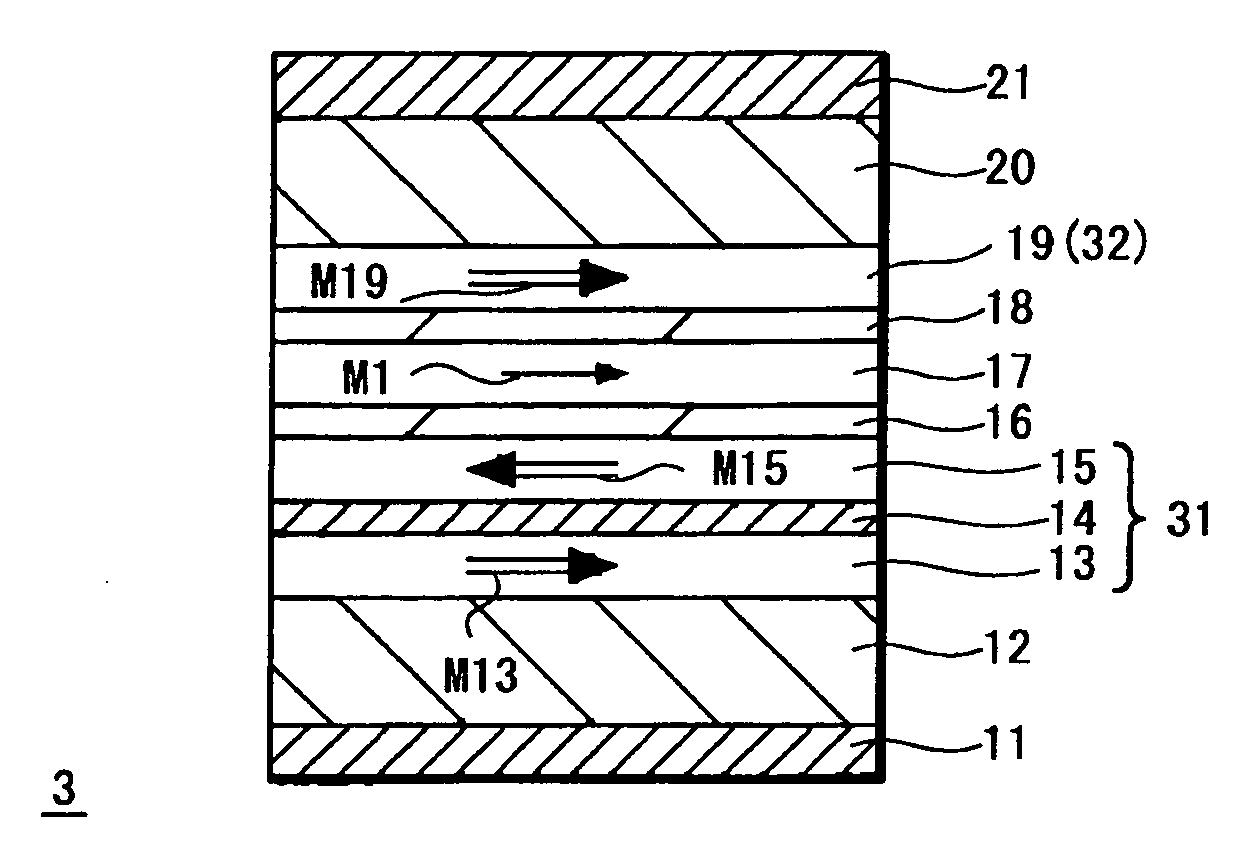
[0072] According to the present invention, information can be recorded by inverting the direction of the storage layer of the storage element based on the aforementioned spin injection. The storage layer is made of a magnetic material such as a ferromagnetic layer and it can store information based on the magnetization state (magnetization direction) of the magnetic material.

[0073] In the fundamental operation to invert a magnetization direction of a magnetic layer based on spin injection, an electric current greater than a certain threshold value is applied to a storage element formed of a giant magnetoresistive effect device (GMR device) or a tunnel magnetoresistive effect device (MTJ device) in the direction perpendicular to the film plane. At that time, a polarity (direction) of the electric current depends on the magnetization direction t...


PUM

PropertyMeasurementUnit
thicknessaaaaaaaaaa
thicknessaaaaaaaaaa
thicknessaaaaaaaaaa

Abstract

A storage element 3 has an arrangement in which magnetization fixed layers 31 and 32 are provided above and below a storage layer 17 for storing information based on the magnetization state of a magnetic material through intermediate layers 16 and 18, directions of magnetizations M15 and M19 of ferromagnetic layers 15 and 19 closest to the storage layer 17 of the magnetization fixed layers 31 and 32 above and below the storage layer 17 are opposite to each other, the two intermediate layers 16 and 18 above and below the storage layer 17 have a significant difference between sheet resistivity values thereof and in which the direction of a magnetization M1 of the storage layer 17 is changed with application of an electric current to the lamination layer direction to record information on the storage layer 17.

Description

CROSS REFERENCES TO RELATED APPLICATIONS [0001] The present invention contains subject matter related to Japanese Patent Application JP 2004-277601 filed in the Japanese Patent Office on Sep. 24, 2004, the entire contents of which being incorporated herein by reference. BACKGROUND OF THE INVENTION [0002] 1. Field of the Invention [0003] The present invention relates to a storage element composed of a storage layer to store therein the magnetization state of a ferromagnetic layer as information and a magnetization fixed layer whose direction of magnetization is fixed, the direction of the magnetization of the storage layer being changed with application of an electric current and a memory including this storage element. More particularly, the present invention is suitable for use as the application to a nonvolatile memory. [0004] 2. Description of the Related Art [0005] In information equipment such as a computer, a DRAM (dynamic random-access memory) operable at a high speed and whi...

Claims


Application Information

Patent Timeline
Patent Type & Authority Applications(United States)
IPC IPC(8): G11B5/127
CPCG11C11/16
Inventor HOSOMI, MASANORIOHBA, KAZUHIROKANO, HIROSHI
Owner SONY CORP
Why Eureka
Try Eureka