

Hologram recording medium and hologram record-reproduction device
- Summary
- Abstract
- Description
- Claims
- Application Information
AI Technical Summary
Benefits of technology
Problems solved by technology
Method used
Image

Examples
first embodiment
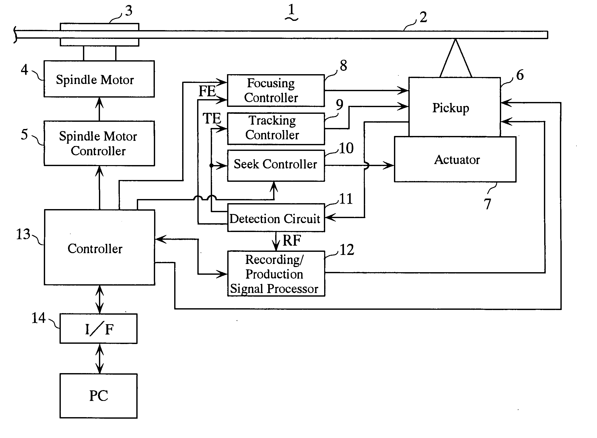
[0055] the hologram recording and reproduction device in accordance with the present invention will be explained by using the drawings.
[0056] The hologram recording and reproduction device of the first embodiment uses a replaceable hologram recording medium of an optical disk type. In this device, data having a prescribed special pattern different from the light image (referred to hereinbelow as a recording pattern) generated by spatial light modulator based on the recording data during recording are recorded in the prescribed address position of the hologram recording medium. During recording or during reproduction, fine adjustment of servo control of focusing or tilting of the hologram recording medium is conducted by using the pattern of those data (this pattern will be referred to as “special pattern” in order to distinguish it from the usual recording pattern of the recording data).
[0057] In the present embodiment, data having the special pattern are recorded in the address po...
second embodiment
[0136] The hologram recording and reproduction device of the second embodiment will be described below.
[0137] The difference between the hologram recording and reproduction device of the second embodiment and the hologram recording and reproduction device of the first embodiment is in that a hologram recording medium 2′ shown in FIG. 13 is used.
[0138] In the hologram recording medium 2′ shown in FIG. 13, the thickness of a hologram recording layer 203 located on the outer periphery of the disk in the hologram recording medium 2 shown in FIG. 3 is about half that of the portions on the inner side thereof. This area 15 with decreased thickness is considered as an area 2D (referred to as the special zone hereinbelow) for recording the data necessary for recording and reproducing the recording data such as directories or management data. Special data having the above-described special patterns for conducting fine adjustment of tilting and focusing or fine adjustment of the wavelength o...
third embodiment
[0146] The hologram recording and reproduction device of the third embodiment will be explained below.
[0147] The hologram recording and reproduction device of the third embodiment employs a method of increasing the number of pixels per 1 bit to the management data and increases the reliability of reproducing the management data, which are more important then the usual recording data.
[0148] In the example explained below, the hologram recording and reproduction device of the third embodiment uses the hologram recording medium 2′ shown in FIG. 13, but the hologram recording medium 2 shown in FIG. 3 may also be used.
[0149]FIG. 15 shows an example of the recording pattern of management data recorded and reproduced in the hologram recording and reproduction device of the third embodiment.
[0150] The recording pattern of the management data shown in the same figure is obtained by using only the right-side area in the method of allocating four pixels per 1 bit shown in FIG. 6 and conduct...
PUM
 Abstract
Description
Claims
Application Information