Cutting insert and milling tool

Active Publication Date: 2006-06-01
KYOCERA CORP
View PDF5 Cites 23 Cited by
  • Summary
  • Abstract
  • Description
  • Claims
  • Application Information

AI Technical Summary

Benefits of technology

[0048] According to the invention, rough cutting is carried out with a milling tool having a cutting insert, and a finishing cut is carried out with a milling tool for finishing. As described above, by using a cutting insert according to the invention it is possible to improve the machined surface roughness of a machined wall face after cutting in a rough-cutting st

Problems solved by technology

In machining where flatness is important, the machined wall face becoming a convexly curved face projecting with progress from the sides to the center like this not only impairs the quality of the appearance of the product, but also, because a re-finishing step becomes necessary, entails excessive machining time and machining cost, and has been problematic from the point of view of machining efficiency.
However, when a milling tool fitted with a cutting insert whose main cutting edge swells as disclosed in Japanese Examined Patent Publication No. 3085686 is used, although when the dimensions of the cutting insert are accurately controlled and the cutting insert is mounted to the holder properly it is possible to co

Method used


Image

  • Cutting insert and milling tool
  • Cutting insert and milling tool
  • Cutting insert and milling tool

Examples


first embodiment

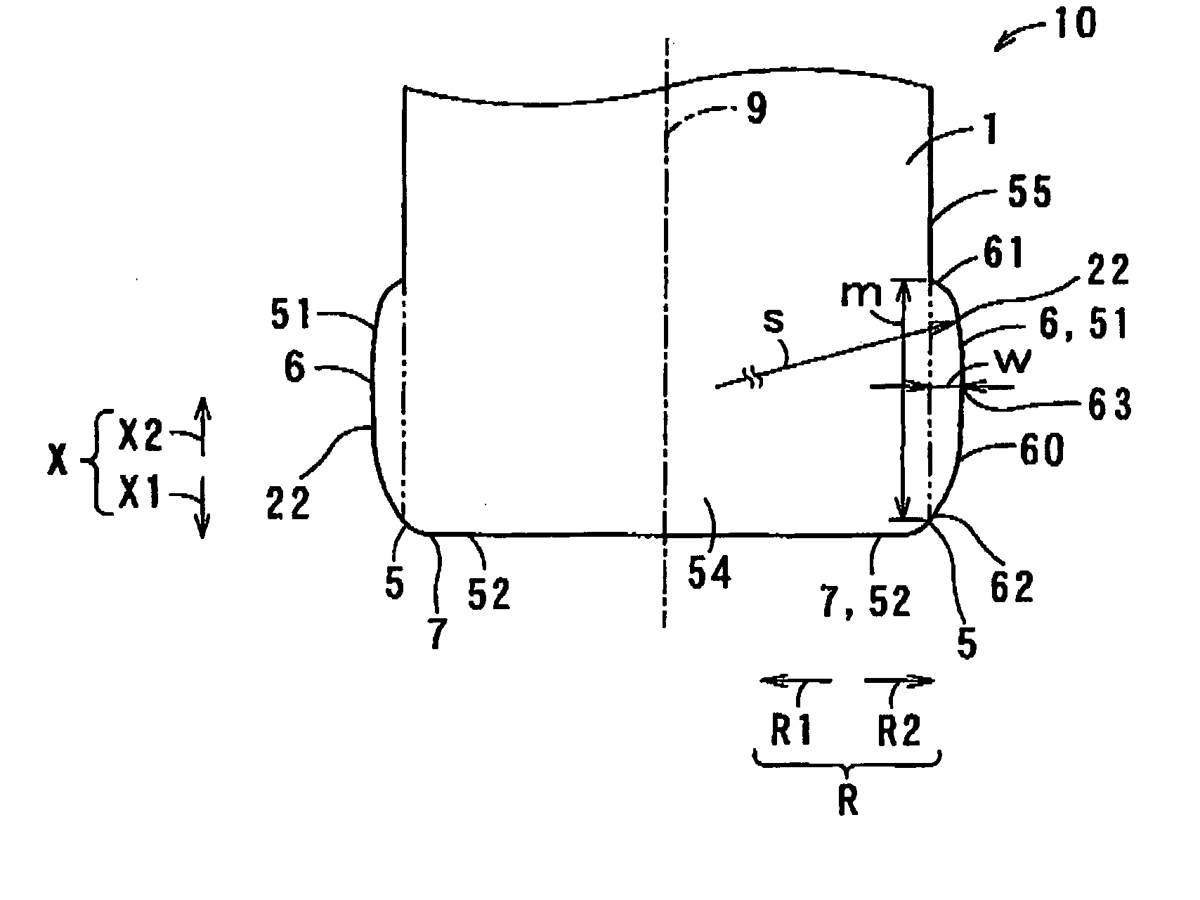
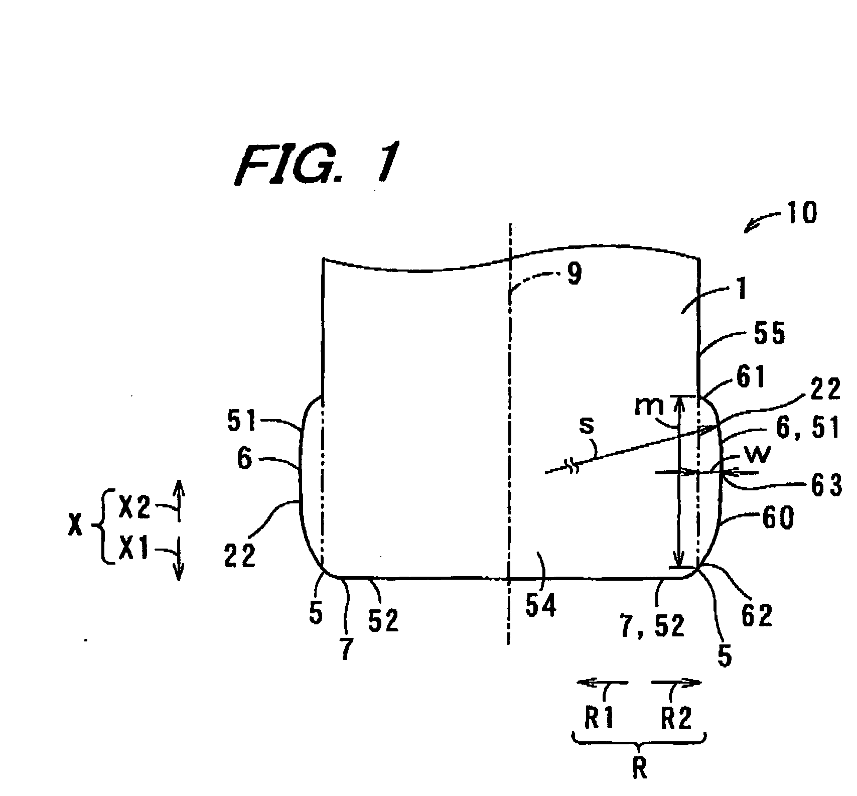
[0075] An end mill 10 according to the invention is a substantially cylindrical milling tool that has a main cutting edge 6 at its circumferential periphery and rotates about an axis of rotation 9. While the end mill 10 is rotated about the axis of rotation 9 by a milling machine or the like, the main cutting edge 6 makes contact with a workpiece and discretely cuts the workpiece. Accordingly it is possible to cut the workpiece to a predetermined shape.

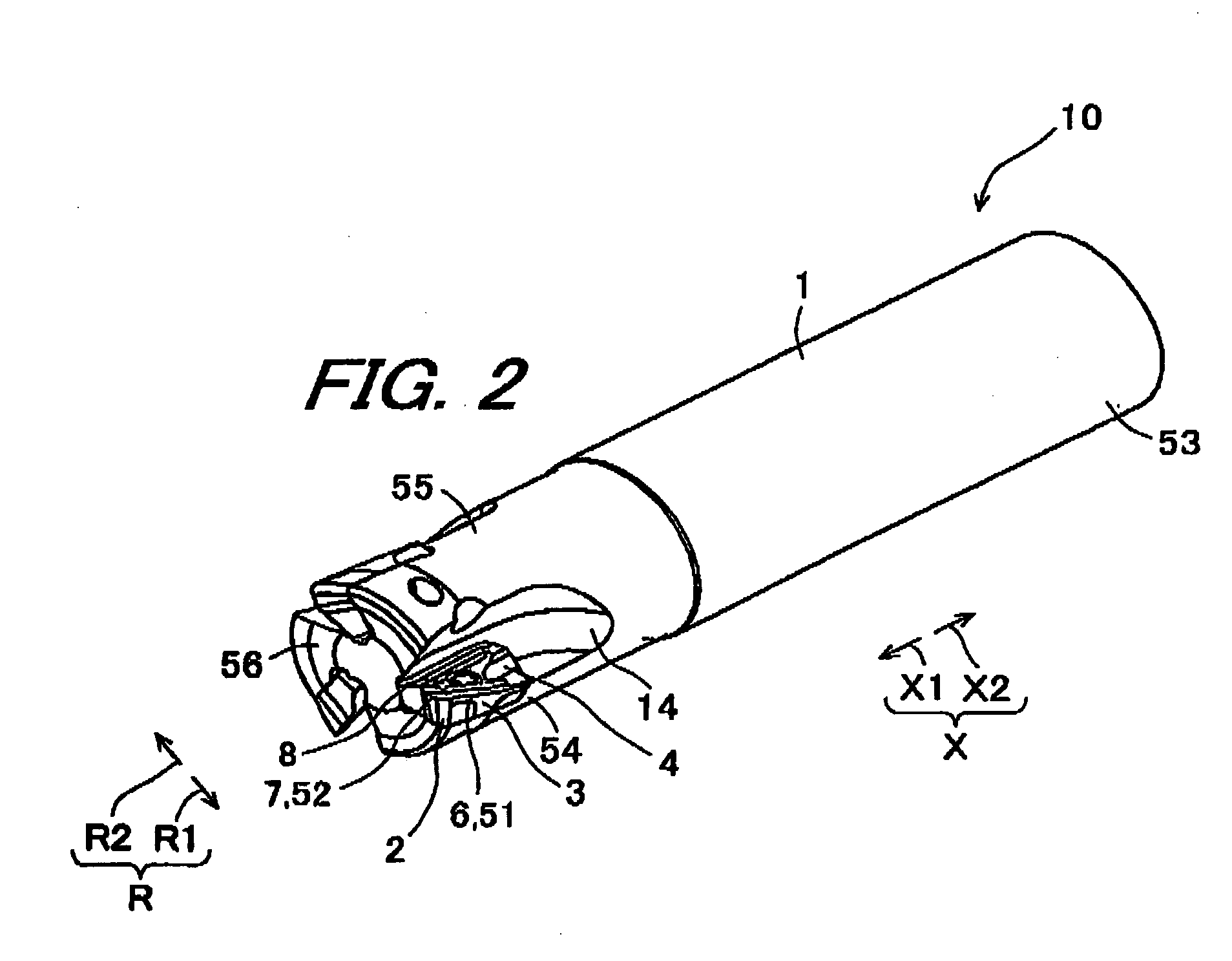
[0076] The end mill 10 of this embodiment is made up of a cutting insert (hereinafter abbreviated to insert) 2 on which are formed a long-side cutting edge 51 constituting the main cutting edge 6 and a short-side cutting edge 52 constituting a flat cutting edge 7, and an end mill holder (hereinafter abbreviated to holder) 1 to which the insert 2 is removably fitted. In this embodiment the holder 1 is constructed so that a plurality of for example three inserts 2 can be fitted to it.

[0077] The holder 1 is formed in an approximately cy...

second embodiment

[0161] In this second embodiment, the sectional shape of the locus of rotation 422 of the main cutting edge 406 slants in the outward holder radial direction R2 with progress in a straight line from a holder axial direction tip end part 462 toward a holder axial direction center part 463, and slants back in the inward holder radial direction R1 with progress in a straight line from the holder axial direction center part 463 toward a holder axial direction base end part 461.

[0162] In this case of the holder axial direction middle part 460 Of the main cutting edge 406 projecting further in the outward holder radial direction R2 than the holder axial direction base end parts 461, 462 also, the same effects as those of the first embodiment can be obtained.

[0163] Besides this the sectional shape of the locus of rotation of the main cutting edge may alternatively follow a gentle curve other than a circular arc, or may extend along a line consisting of a combination of a plurality of stra...

third embodiment

[0165] In the third embodiment, at the location in contact with the workpiece 11, the holder axial direction base end part 561 of the main cutting edge 506 is further inward from the workpiece in the holder radial direction R than the holder axial direction tip end part 562 of the main cutting edge 506.

[0166] In the third embodiment, compared to the rest of the main cutting edge 506, a holder tip end side portion 511 of the holder axial direction middle part 560 of the main cutting edge 506 projects farthest in the outward holder radial direction R2. Consequently, even when the holder 501 bends during cutting, the projection amount by which the holder axial direction base end part 561 of the main cutting edge 506 projects beyond the holder axial direction tip end part 562 of the main cutting edge 506 in the outward holder radial direction R2 can be made small. Therefore, the affect of bending of the holder 1 can be made small, and the machined surface roughness of the machined wall ...


PUM

PropertyMeasurementUnit
Lengthaaaaaaaaaa
Lengthaaaaaaaaaa
Radiusaaaaaaaaaa

Abstract

A milling tool includes a cutting tool insert, roughly plate-shaped and having a rake face on an upper face and a flank on a side face and a main cutting edge at an intersection ridge line part at the intersection of the rake face and the flank, fitted in the periphery of a substantially cylindrical holder removably and so that an axial rake angle of the cutting edge ridge line of the main cutting edge is positive. When the cutting tool insert is rotated about the axis of rotation of the holder, the shape of the locus of rotation of the main cutting edge in a section parallel to the axis of rotation is made an approximate circular arc shape swelling outward with progress from the ends to the center.

Description

BACKGROUND OF THE INVENTION [0001] 1. Field of the Invention [0002] The present invention relates to a milling tool used as a rotating bit in a machine tool such as a machining center. [0003] 2. Description of the Related Art [0004] There has been known end mills in which a cutting insert having a shape of an approximate parallelogram is fitted into a tip part of a holder used as a rotating tool in machining with machine tools such as machining centers. The cutting insert is fitted into the holder so that a long side is disposed at the periphery of the end mill as a main cutting edge, a short side is disposed at the tip of the end mill as a flat cutting edge, and the main cutting edge slants at an angle, called the axial rake angle, to the axis of rotation of the holder. [0005] Conventionally, a cutting insert in a plan view of which a main cutting edge is formed in a straight line have been used. However, when the cutting insert is fitted in a holder with an axial rake angle as des...

Claims


Application Information

Patent Timeline
IPC IPC(8): B23C1/00
CPCB23C3/28B23C5/10B23C5/109B23C5/2213B23C2200/123B23C2200/203Y10T407/23B23C2200/246Y10T407/1908Y10T407/235Y10T409/303808Y10T407/22Y10T407/1906B23C2200/208
Inventor NISHIO, MITSUHIROHATTA, KAORUKOJIMA, YOSHIHIDE
Owner KYOCERA CORP
Why Eureka
Try Eureka